
Page 930 - 5G Basics - Core Network Aspects
P. 930
2 Transport aspects
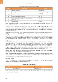
Table 12-28 – O-VECTOR-FEEDBACK message
Field Field name Format
1 Message descriptor Message code
2 Vectoring report control parameters Vectoring report configuration
descriptor
3 Reference superframe count Two bytes
4 US SOC tone repetition rate (pus) One byte
5 VFRB update parameters (q, s and reporting mode) One byte
6 VFRB shift period (z) One byte
7 Vectored bands Variable
Field 1 "Message descriptor" is a unique one-byte code (0316) that identifies the message. See Table 12-7
for a complete list of codes.
Field 2 "Vectoring feedback report control parameters" indicates values of the vectoring feedback report
control parameters requested by the FTU-O for the FTU-R to apply in the vectoring feedback report. The
format of the control parameters shall be as defined in the vectoring feedback report configuration
descriptor, Table 11-41.
Field 3 "Reference superframe count" indicates the superframe count from which the report shall start
(CNTSF ), as defined in clause 10.3.2.5.2. The count shall be represented as a two-byte unsigned integer.
0
Field 4 "US SOC tone repetition rate (pus)" indicates the tone repetition rate (pus) of SOC normal bit mapping
to be used by the FTU-R for vectoring feedback reporting in the subsequent R-VECTOR-FEEDBACK message.
The field shall contain the upstream value pus defined in clause 10.2.2.2.1, represented as an unsigned
integer.
Field 5 "VFRB update parameters (q, s and reporting mode)" indicates control parameters q (VF sample
update period) and s (frequency shift step) facilitating, respectively, VFRB time identification
(see clause 10.3.2.5.2) and VFRB frequency identification (see clause 10.3.2.5.1). Bits [3:0] indicate the
value of q represented as an unsigned integer, and bits [7:5] indicate the value of s represented as an
unsigned integer. Bit [4] indicates the reporting mode. If set to 1, the VFRB shall contain DFT output
samples, otherwise the VFRB shall contain clipped error samples. Other bits are reserved by ITU-T.
Field 6 "VFRB shift period (z)" indicates control parameter facilitating VFRB time identification
(see clause 10.3.2.5.2), represented as an unsigned integer.
Field 7 "Vectored bands" describes the number of vectored bands and the start and stop frequencies of the
vectored bands requested in VFRB represented in a format of band descriptor (see Table 12-21). The size of
the field depends on the number of reported vectored bands.
12.3.3.2.7 R-ACK
R-ACK is a one-byte SOC message that acknowledges correct reception of the O-VECTOR-FEEDBACK
message. The format shall be as defined in Table 12-29.
Table 12-29 – R-ACK message
Field Field name Format
1 Message descriptor Message code
Field 1 "Message descriptor" is a unique one-byte code (8216) that identifies the message. See Table 12-7
for a complete list of codes.
920