Page 925 - 5G Basics - Core Network Aspects
P. 925
Transport aspects 2
The FTU-R shall comply with the conveyed PSD mask at all times. In addition, FTU-R shall comply with the
requirements in the RFI bands and IAR bands determined during the ITU-T G.994.1 handshake phase, as
specified in clause 12.3.2.1, and with the UPBO requirements, which may further reduce the upstream
transmit PSD, as specified in clause 7.3.1.4.
Field 6 "Channel discovery downstream PSD (CDPSDds)" indicates the PSD at the U interface in the
downstream direction during the early stages of the channel discovery phase (see clause 12.3.3.3) using
breakpoints. The "PSD descriptor" format specified in Table 12-22 shall be used, and the number of
breakpoints being described shall be from 2 to 32. The only valid PSD values obtained by the receiver using
the interpolation procedure specified are for those subcarriers that belong to the SUPPORTEDCARRIERSds
set, excluding the RFIBANDS and IARBANDS communicated during the ITU-T G.994.1 handshake phase; PSD
values out of this set shall be ignored by the receiver. The valid CDPSDds values shall be below the
downstream transmit PSD mask (Field 4). The FTU-O shall set the CDPSDds breakpoints such that the valid
values of CDPSDds obtained by the receiver either directly or by interpolation do not deviate from the
actual values of the transmit PSD, as measured on the reference impedance at the U interface, by more
than 1 dB. If 32 breakpoints are insufficient to describe the entire SUPPORTEDCARRIERSds set, the field
shall indicate the CDPSDds starting from the lowest index of the SUPPORTEDCARRIERSds set and cover as
much spectrum as possible.
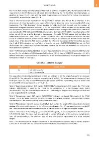
Field 7 "UPBO reference PSD (UPBOPSD)" contains the parameters to compute the reference PSD that shall
be used for the calculation of UPBO as specified in clause 7.3.1.4. A set of UPBOPSD parameters (a′, b′) is
defined for the entire upstream band. The values of a′ and b′ shall be coded as 12-bit unsigned integers and
formatted as shown in Table 12-23.
Table 12-23 – UPBOPSD descriptor
Byte Content of field
1-3 bits 0-11: value of a′
bits 12-23: value of b′
The value of a is obtained by multiplying a′ by 0.01 and adding it to 40. The range of values for a is between
40 and 80.95. The value of b is obtained by multiplying b′ by 0.01. This allows values of b between 0 and
40.95 (see clause 7.3.1.4). In case UPBO shall not be applied, all 12 bits representing values a′ and b′ shall
be set to ZERO (which corresponds to a = 40, b = 0).
Field 8 "Downstream minimum SNR margin (MINSNRMds)" is the minimum SNR margin the FTU-R shall
tolerate. MINSNRMds is used by the FTU-R in the generation of a loss-of-margin (lom) defect
(see clause 11.3.1.3). The field shall be formatted as a 16-bit unsigned integer with LSB weight of 0.1 dB and
a valid range between 0 and 31 dB.
Field 9 "Downstream target SNR margin (TARSNRMds)" indicates the target SNR margin of the FTU-R
receiver. This is the SNRM value that the FTU-R receiver shall achieve, or better, to successfully complete
the initialization. The format used shall be the same as for field 8.
Field 10 "Downstream transmit window length (ds)" shall contain the length of the downstream transmit
window, (ds), expressed in samples at the reference sampling rate 2N × Δf corresponding to the used IDFT
size. The valid values shall be as defined in clause 10.4.4 and coded as an eight-bit unsigned integer.
Field 11 "Initial value of the time gap Tg1'" indicates the time gap Tg1' to be used by the FTU-R at the start of
R-P-VECTOR 1 stage. The value shall be expressed in number of samples at the reference sampling rate
(2N x f) corresponding to the used IDFT size (N). The value shall be represented as a 16-bit unsigned
integer.
NOTE 2 – The initial value of the time gap is determined by the VCE to cover the expected range of the loop length for
a particular DP. An initial value that corresponds to maximum expected loop length is recommended.
915

