
Page 929 - 5G Basics - Core Network Aspects
P. 929
Transport aspects 2
value shall be coded as a 16-bit number. The valid range of values is from 0 dB to 128 dB with a 0.1 dB step.
This value may be same or different from the value reported by the FTU-R in R-MSG 1 message and shall be
used by the FTU-R to determine the final UPBOMASK, as specified in clause 7.3.1.4.2.2. This updated
UPBOMASK shall be used to form the upstream PSD mask applied to CDPSDus and MREFPSDus (field 3 of R-
UPDATE message and field 3 of R-PRM message).
Field 3 "Upstream PSD ceiling (MAXMASKus)" indicates the PSD ceiling level of the upstream transmit PSD
mask. If this level is lower than the PSDMASKus indicated in O-SIGNATURE, the FTU-R shall apply this ceiling
level to PSDMASKus. Otherwise, the FTU-R shall ignore this field and continue with PSDMASKus. This ceiling
level shall be used to form the upstream PSD mask applied to CDPSDus and MREFPSDus (field 3 of R-
UPDATE message and field 3 of R-PRM message). This field shall be coded as a 16-bit value with LSB weight
of -0.1dB. The valid range is from 0dBm/Hz to –90 dBm/Hz. A special value 100016 shall indicate no limit to
the upstream PSD ceiling level (under the constraints of the upstream transmit PSD mask).
Field 4 "Final time gap correction ΔTg1'" indicates the final correction of the time gap Tg1' relative to the
current Tg1' value expressed in samples, at the sampling rate corresponding to the used IDFT size. The new
value of Tg1' is equal to the current value of Tg1' plus ΔTg1'. The value shall be encoded in a 16-bit field using
two’s complement format.
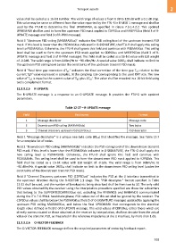
12.3.3.2.5 R-UPDATE
The R-UPDATE message is a response to an O-UPDATE message. It provides the FTU-O with updated
parameters.
Table 12-27 – R-UPDATE message
Field Field name Format
1 Message descriptor Message code
2 Downstream PSD ceiling (MAXMASKds) Two bytes
3 Channel Discovery upstream PSD (CDPSDus) PSD descriptor
Field 1 "Message descriptor" is a unique one-byte code (8116) that identifies the message. See Table 12-7
for a complete list of codes.
Field 2 "Downstream PSD ceiling (MAXMASKds)" indicates the PSD ceiling level of the downstream transmit
PSD mask. If this level is lower than the PSDMASKds indicated in O-SIGNATURE, the FTU-O shall apply this
new ceiling level to PSDMASKds. Otherwise, the FTU-O shall ignore this field and continue with
PSDMASKds. This ceiling level shall be used to form the downstream PSD mask applied to V2PSDds. This
field shall be coded as a 16-bit value with LSB weight of -0.1dB. The valid range is from 0dBm/Hz to
−90 dBm/Hz. A special value 100016 shall indicate no limit to the downstream PSD ceiling level (under the
constraints of the downstream transmit PSD mask).
Field 3 "Channel Discovery upstream PSD (CDPSDus)" indicates the PSD at the U interface transmitted in
the upstream direction during the R-VECTOR 1.1 stage. The "PSD descriptor" format specified in Table
12-22 shall be used, and the number of breakpoints being described shall be from two to 32. The only valid
PSD values obtained by the receiver using the interpolation procedure specified are those for subcarriers
that belong to the SUPPORTEDCARRIERSus set, excluding the RFIBANDS and IARBANDS communicated
during the ITU-T G.994.1 handshake phase; PSD values out of this set shall be ignored by the receiver. The
CDPSDus values shall be below the PSDMASKus (field 5 of O-SIGNATURE message) updated by applying the
upstream PSD ceiling MAXMASKus, and below the final UPBOMASK that corresponds to the electrical
length value defined in field 2 of O-UPDATE message. The valid values of CDPSDus, either those which are
directly communicated or those obtained at the receiver by interpolation, shall not deviate from the actual
value of the transmit PSD, as measured in the reference impedance at the U interface, by more than 1 dB.
12.3.3.2.6 O-VECTOR-FEEDBACK
The O-VECTOR-FEEDBACK message defines the required parameters of vectoring feedback report.
919