
Page 928 - 5G Basics - Core Network Aspects
P. 928
2 Transport aspects
Field 1 "Message descriptor" is a unique one-byte code (8016) that identifies the message. See Table 12-7
for a complete list of codes.
Field 2 "Estimate of electrical length" conveys the estimate of the electrical length, expressed in dB (see
clause 7.3.1.4.2.1), as determined by the FTU-R. The value shall be coded as a 16-bit number with LSB
weight of 0.1dB. The valid range of the electrical length is from 0 dB to 128 dB in 0.1 dB steps. Using this
estimate of the electrical length, the FTU-R shall derive the initial upstream power back-off mask
(UPBOMASK), as described in clause 7.3.1.4.2.2.
Field 3 "Startup upstream PSD (STARTPSDus)" indicates the PSD at the U interface transmitted in the
upstream direction during the Channel Discovery 1 stage. The "PSD descriptor" format specified in Table
12-22 shall be used, and the number of breakpoints being described shall be from 2 to 32. The only valid
PSD values obtained by the receiver using the interpolation procedure specified are those for subcarriers
that belong to the SUPPORTEDCARRIERSus set, excluding the RFIBANDS and IARBANDS communicated
during the ITU-T G.994.1 handshake phase; PSD values out of this set shall be ignored by the receiver. The
STARTPSDus values shall be less than or equal to the PSDMASKus (field 5 of O-SIGNATURE message), and
below the initial UPBOMASK that corresponds to the electrical length value defined in field 2. The valid
values of STARTPSDus, either those which are directly communicated or those obtained at the receiver by
interpolation, shall not deviate from the actual value of the transmit PSD, as measured in the reference
impedance at the U interface, by more than 1 dB.
Field 4 "Upstream transmit window length (us)" contains the length of the transmit window that shall be
used in the upstream direction during the initialization and showtime. The value shall be expressed in the
samples of the upstream sampling rate corresponding to the profile used (communicated during the ITU-T
G.994.1 handshake phase). The range of valid values and format shall be the same as for field 10 of the
O-SIGNATURE message.
Field 5 "DS SOC symbol repetition rate (R)" indicates the recommended DS SOC symbol repetition rate to
be used in subsequent initialization procedures (valid values are defined for the ITU-T G.994.1 handshake –
see Table 12-10). A special value FF16 indicates that FTU-R has no particular recommendation.
Field 6 "DRR configuration data" is two bytes long and conveys the FTU-R DRR configuration data (as
received from the L2+ function at the FTU-R). Based on this information, the DRA determines the size (NRM)
of the resources metric in the RMC upstream dynamic resource report (DRRus) command sent in the
upstream RMC (see Table 9-17). The DRA includes the value of NRM in DRRus.request (NDRR, NRM) sent to the
FTU-O (see Table 8-3). The FTU-O may use the value of NRM to determine the upstream KRMC to be conveyed
in O-PMS message. The DRR configuration data shall be represented as two-byte field, formatted as defined
in Table Y.2.
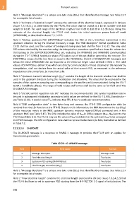
12.3.3.2.4 O-UPDATE
The O-UPDATE message is a response to R-MSG 1 message. It provides the FTU-R with an update for
transmission parameters.
Table 12-26 – O-UPDATE message
Field Field name Format
1 Message descriptor Message code
2 Final electrical length Two bytes
3 Upstream PSD ceiling (MAXMASKus) Two bytes
4 Final time gap correction (ΔTg1') Two bytes
Field 1 "Message descriptor" is a unique one-byte code (0216) that identifies the message. See Table 12-7
for a complete list of codes.
Field 2 "Final electrical length" contains the electrical length expressed in dB (see clause 7.3.1.4.2.2) that
the FTU-R shall use to set its upstream PSD starting from the R-P-VECTOR 1-1 signal of initialization. The
918