
Page 927 - 5G Basics - Core Network Aspects
P. 927
Transport aspects 2
Field 21 "UPBO reference electrical length (UPBOKLREF)" contains the kl0_REF parameter for the calculation
of UPBO as specified in clause 7.3.1.4.2.2 for the entire upstream band.
The value shall be coded as an eight-bit unsigned integer with a LSB weight of 0.1 dB. The valid range of
values is from 0 to 25.5 dB with a 0.1 dB step. The use of the special value 0 is described in
clause 7.3.1.4.2.2.
Field 22 "Number of downstream initialization data symbols for SNR estimation (Sds_snr)" conveys the
number of downstream data symbols in a logical frame that may be used during the initialization for SNR
estimation starting from the O-P-PRM-UPDATE 1. The value of Sds-snr shall be higher or equal to downstream
MNDSNOI. The value shall be coded as an eight-bit unsigned integer. The valid range of values is
from 4 to 32.
NOTE – The DRA should configure the other showtime lines in the vectoring group to transmit at least Sds-snr data
symbols during the first symbol positions in the downstream logical frame.
Field 23 "Upstream Maximum Aggregate Transmit Power (MAXATPus)" is the maximum value of
the aggregate transmit power during initialization and the maximum value of the ACTATPus
(see clause 11.4.1.5) during showtime that the FTU-R shall be allowed to transmit. The field shall
be formatted as a 16-bit signed integer with LSB weight of 0.1 dBm and a valid range from –31 to
31 dBm.
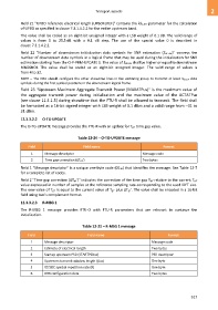
12.3.3.2.2 O-TG-UPDATE
The O-TG-UPDATE message provides the FTU-R with an update for Tg1' time gap value.
Table 12-24 – O-TG-UPDATE message
Field Field name Format
1 Message descriptor Message code
2 Time gap correction (ΔTg1') Two bytes
Field 1 "Message descriptor" is a unique one-byte code (0116) that identifies the message. See Table 12-7
for a complete list of codes.
Field 2 "Time gap correction (ΔTg1')" indicates the correction of the time gap Tg1' relative to the current Tg1'
value expressed in number of samples at the reference sampling rate corresponding to the used IDFT size.
The new value of Tg1' is equal to the current value of Tg1' plus ΔTg1'. The value shall be encoded in a 16-bit
field using two’s complement format.
12.3.3.2.3 R-MSG 1
The R-MSG 1 message provides FTU-O with FTU-R parameters that are relevant to continue the
initialization.
Table 12-25 – R-MSG 1 message
Field Field name Format
1 Message descriptor Message code
2 Estimate of electrical length Two bytes
3 Startup upstream PSD (STARTPSDus) PSD descriptor
4 Upstream transmit window length (us) One byte
5 DS SOC symbol repetition rate (R) One byte
6 DRR configuration data Two bytes
917