
Page 934 - 5G Basics - Core Network Aspects
P. 934
2 Transport aspects
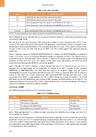
Table 12-36 – Gain descriptor
Byte Content of the field
1-2 MEDLEYds set index (m0) of first subcarrier described
3-4 MEDLEYds set index (m1) of last subcarrier described
5 Gain compensation factor for subcarrier with MEDLEYds set index m0
6 Gain compensation factor for subcarrier with MEDLEYds set index m0+1
... ....
5+m1-m0 Gain compensation factor for subcarrier with MEDLEYds set index m1
NOTE – The gain compensation factor shall be included by ascending MEDLEYds set index.
Field 5 "BLACKOUTus set" indicates the set of upstream blackout subcarriers using a tone descriptor format
presented in Table 12-34.
The first byte of the tone descriptor shall contain the number of tones selected by the FTU-O. If this
number is zero, there shall be no further bytes in the descriptor. If the number of tones is not equal to zero,
each group of three consecutive bytes in the descriptor describes two tones. If the number of tones is odd,
the last 12 bits in the last field shall be set to ZERO. The FTU-R shall support 255 upstream blackout
subcarriers.
Field 6 "Upstream reference PSDMASK (MREFPSDMASKus)" indicates the MREFPSDMASKus as defined in
clause 7.3.2 (Table 7-1) on all proposed MEDLEYus subcarriers indicated in field 2. The format shall be
presented using the "PSD descriptor" format defined in Table 12-22 and the number of breakpoints being
described shall be from two to 32. The update of PSD mask values obtained by the FTU-R on other
subcarriers than the proposed MEDLEYus set shall be ignored
Field 7 "Request for retrain" indicates a retrain request from the FTU-O. The FTU-O can use it if it is
expected that an optimization of the transmitter or receiver front end is needed for the proposed
MREFPSDds or MREFPSDMASKus. The field shall be coded as an unsigned integer with the value 0
indicating that no retrain is requested and with the value 1 if a retrain is requested. If the FTU-O requests a
retrain, it shall abort the current initialization after receiving R-PRM message and shall start a new
initialization from QUIET 1 stage (without the ITU-T G.994.1 phase) by sending O-P-QUIET-1. The FTU-R
shall abort the current initialization after sending R-PRM message and shall transition to R-P-QUIET1. The
negotiated values of the previous ITU-T G.994.1 phase shall be used in the new initialization. The timeout
counter for initialization procedure shall be restarted.
12.3.3.2.12 R-PRM
The R-PRM message provides the FTU-O parameter update.
Table 12-37 – R-PRM message
Field Field name Format
1 Message descriptor Message code
2 Pilot symbol configuration One byte
3 US reference PSD (MREFPSDus) PSD descriptor
4 Final MEDLEY set of active US subcarriers Band descriptor
Field 1 "Message descriptor" is a unique one-byte code (8516) that identifies the message. See Table 12-7
for a complete list of codes.
Field 2 "Pilot symbol configuration" indicates the requested configuration of pilot symbols per superframe
as defined in clause 10.4.5.1. It is represented as an unsigned integer with valid values 0, 1 or 2. If the value
is 0, a pilot symbol is requested in the last logical frame of the superframe; if the value is 1, pilot symbols
are requested in every other logical frame of the superframe, if the value is 2, pilot symbols are requested
in all logical frames of the superframe.
924