
Page 924 - 5G Basics - Core Network Aspects
P. 924
2 Transport aspects
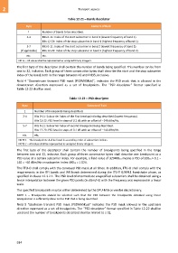
Table 12-21 – Bands descriptor
Byte Content of field
1 Number of bands to be described.
2-4 Bits 0-11: Index of the start subcarrier in band 1 (lowest frequency of band 1).
Bits 12-23: Index of the stop subcarrier in band 1 (highest frequency of band 1).
5-7 Bits 0-11: Index of the start subcarrier in band 2 (lowest frequency of band 2).
(if applicable) Bits 12-23: Index of the stop subcarrier in band 2 (highest frequency of band 2).
etc. etc.
NOTE – All values shall be represented as unsigned binary integers.
The first byte of the descriptor shall contain the number of bands being specified. This number can be from
one to 32, inclusive. Each group of three consecutive bytes shall describe the start and the stop subcarrier
index of the band, both in the range between 43 and 4 095, inclusive.
Field 4 "Downstream transmit PSD mask (PSDMASKds)", indicates the PSD mask that is allowed in the
downstream direction expressed as a set of breakpoints. The "PSD descriptor" format specified in
Table 12-22 shall be used.
Table 12-22 – PSD descriptor
Byte Content of field
1 Number of breakpoints being described.
2-4 Bits 0-11: Subcarrier index of the first breakpoint being described (lowest frequency).
Bits 12-23: PSD level in steps of 0.1 dB with an offset of −140 dBm/Hz.
5-7 Bits 0-11: Subcarrier index of second breakpoint being described.
Bits 12-23: PSD level in steps of 0.1 dB with an offset of −140 dBm/Hz.
etc. etc.
NOTE 1 – The breakpoints shall be listed in ascending order of subcarriers indices.
NOTE 2 – All values shall be represented as unsigned binary integers.
The first byte of the descriptor shall contain the number of breakpoints being specified in the range
between two and 32, inclusive. Each group of three consecutive bytes shall describe one breakpoint as a
PSD value at a certain subcarrier index. For example, a field value of 32040016 means a PSD of 32016 × 0.1 −
140 = −60 dBm/Hz on subcarrier index 40016 = 1 024.
The FTU-O shall comply with the conveyed PSD mask at all times. In addition, FTU-O shall comply with the
requirements in the RFI bands and IAR bands determined during the ITU-T G.994.1 handshake phase, as
specified in clause 12.3.2.1. The PSD level of intermediate unspecified subcarriers shall be obtained using a
linear interpolation between the given PSD points (in dBm/Hz) with the frequency axis expressed in a linear
scale.
The specified breakpoints may be either determined by the DPU-MIB or vendor discretionary.
NOTE 1 – Breakpoints should be selected such that the PSD between the breakpoints obtained using linear
interpolation is sufficiently close to the PSD that is being described.
Field 5 "Upstream transmit PSD mask (PSDMASKus)" indicates the PSD mask allowed in the upstream
direction expressed as a set of breakpoints. The "PSD descriptor" format specified in Table 12-22 shall be
used and the number of breakpoints described shall be limited to ≤ 32.
914