
Page 732 - 5G Basics - Core Network Aspects
P. 732
2 Transport aspects
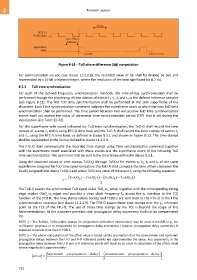
Figure 8-14 – ToD phase difference () computation
For communication via eoc (see clause 11.2.2.8), the recorded value of shall be divided by two and
represented by a 16-bit unsigned integer, where the resolution of the least significant bit is 2 ns).
8.5.3 ToD time synchronization
For each of the defined frequency synchronization methods, the time-of-day synchronization shall be
performed through the processing of time stamps of events t1, t2, t3 and t4 at the defined reference samples
(see Figure 8-13). The first ToD time synchronization shall be performed at the 16th superframe of the
showtime. Each Time synchronization command indicates the superframe count at which the next ToD time
synchronization shall be performed. The time period between two consecutive ToD time synchronization
events shall not exceed the value of parameter time synchronization period (TSP) that is set during the
initialization (see Table 12-42).
For the superframe with count indicated for ToD time synchronization, the ToD-O shall record the time
stamps of events t1 and t4 using RTC-O time base and the ToD-R shall record the time stamps of events t2
and t3, using the RTC-R time base, as defined in clause 8.5.1 and shown in Figure 8-13. The time stamps
shall be represented in the format defined in clause 11.2.2.9.
The FTU-O shall communicate the recorded time stamps using Time synchronization command together
with the superframe count associated with these events and the superframe count of the following ToD
time synchronization. The command shall be sent in the time frame defined in clause 8.5.1.
Using the obtained values of time stamps ToD(t1) through ToD(t4) for events t1, t2, t3 and t4 of the same
superframe assigned for ToD time synchronization, the ToD-R shall compute the time offset between the
locally assigned time stamp ToD(t2) and actual ToD time value of the event t2 using the following equation:
ToD (t 2 ) ToD (t 1 ) ToD (t 4 ) ToD (t 3 )
2
The ToD-R passes the synchronized ToD signal value ToD_sc_value, together with the corresponding timing
edge marker (ToD_sc_edge) and possibly a slave clock frequency fsc across the R interface to the TCE
function of the FTU-R. The time stamp values ToD(t2) and ToD(t3) are sent back to the FTU-O in the Time
synchronization response (see clause 11.2.2.9). The FTU-O passes these time stamps over the O reference
point to the TCE of the FTU-O. The use of these time stamps by the TCE is beyond the scope of this
Recommendation. At the customer premises side, propagation delay asymmetry shall not be compensated
for.
NOTE 1 – The ToD(t2), ToD(t3) time stamps (in conjunction with other information) may be used at the DPU e.g., for
verification purposes or to compensate for propagation delay asymmetry. However, propagation delay asymmetry is
expected to be less than that of VDSL2.
NOTE 2 – The above computation of the offset value is based on the assumption that the downstream and upstream
propagation delays between the U-O and U-R reference points are approximately the same. Any asymmetry in the
propagation delay between the U-O and U-R reference points will result in an error in calculation of the offset value
whose magnitude is approximately:
upstream _ propagatio n _ delay downstream _ propagatio n _ delay
error
2
722