
Page 730 - 5G Basics - Core Network Aspects
P. 730
2 Transport aspects
at a frequency that is an integer multiple of 8 kHz with a frequency of at least fs (PMD sample clock, see
Figure 8-11), with time adjustment to the master clock at each fmc edge.
The FTU-R's PMD sample is assumed to be frequency locked with the FTU-O's PMD sample clock through
loop timing in the FTU-R. To record the time stamps in each of the upstream and downstream transmit
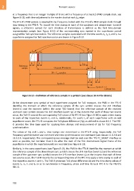
signals, a reference sample for each direction of transmission is defined as the first time-domain
representation sample (see Figure 8-12) of the corresponding sync symbol in the superframe period
assigned for ToD synchronization. The reference samples associated with the time events t1, t2, t3 and t4 in a
superframe assigned for ToD synchronization are shown in Figure 8-13.
L CP L = β
CS
L
Reference CP L
sample Original 2 samplesN CP
2N L samples
CP
Symbol i
Symbol i + 1
G.9701(14)_F8-12
Figure 8-12 – Definition of reference sample in a symbol i (see clause 10.4.4 for details)
At the downstream sync symbol of each superframe assigned for ToD transport, the PMD in the FTU-O
identifies the moment at which the reference sample of the sync symbol crosses the U-O interface
(event t1) and the moment (within the same TDD frame) that the reference sample of the received
upstream sync symbol crosses the U-O interface (event t4); at the instants that each of these two events
occur, the ToD-O records the corresponding ToD values of its RTC-O (see Figure 8-14) to apply a time stamp
to each of the respective events t1 and t4. Additionally, for event t1 of each superframe with an odd
superframe count, the FTU-O computes the ToD phase difference (), as defined in clause 8.5.2. The RTC-
O provides the time base used for applying time stamps and measurement of for ToD frequency
synchronization.
The values of , and t1 and t4 time stamps are transmitted to the FTU-R using, respectively, the ToD
frequency synchronization eoc command and time synchronization eoc command (see clauses 11.2.2.8 and
11.2.2.9, respectively). The corresponding eoc message shall be sent over the TPS-TC_MGMT interface as
soon as possible, but not later than 6 ms after the start of the first downstream logical frame of the
superframe in which the reported events are recorded (see Figure 8-13).
Similarly, in the same superframe (see Figure 8-13), the PMD in the FTU-R identifies the moment at which
the reference sample of the downstream sync symbol crosses the U-R interface (event t2) and the reference
sample of the upstream sync symbol crosses the U-R interface (event t3); at the instants that each of these
two events occur, the ToD-R records the corresponding time of the RTC-R to apply a time stamp to each of
the respective events t2 and t3. The ToD-R processes ToD phase difference and the time stamp values of
events t1, t2, t3 and t4 so as to synchronize in frequency, phase and time its local RTC-R to the FTU-O's
RTC-O.
720