
Page 737 - 5G Basics - Core Network Aspects
P. 737
Transport aspects 2
The polynomial C(D) is the remainder obtained from dividing M ( D) D R FEC by G(D). The arithmetic in this
clause shall be performed in the Galois Field GF(256), where is a primitive element that satisfies the
primitive binary polynomial x 8 x 4 x 3 x 2 1. A data byte (d 7 ,d 6 ,...,d 1 ,d 0 ) is identified with the
Galois Field elementd 7 d 6 ... d d .
0
6
7
1
Parameters NFEC, KFEC and RFEC shall be programmable.
The valid values of RFEC are 2, 4, 6, 8, 10, 12, 14 and 16.
The valid values of NFEC are all integers from 32 to 255, inclusive. An FTU shall support all combinations of
valid values of RFEC and NFEC.
The FEC encoder RS(NFEC, KFEC) shall insert RFEC redundancy bytes after every KFEC bytes, counting from the
first byte of the DTU. The DTU size after FEC encoding is Q×NFEC bytes.
The valid values of FEC encoding parameters for the RMC are specified in clause 9.6.3.
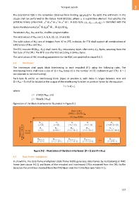
9.4 Interleaver
The interleaver shall apply block interleaving to each encoded DTU using the following rules. The
interleaving block shall have a size of Q × NFEC bytes (Q is the number of FEC codewords per DTU, Q = 1
corresponds to no interleaving).
Each byte Bk within an interleaving block (input at position k, with index k ranges between zero and
Q × NFEC – 1) shall be located at the output of the interleaving function at position l given by the equation:
l = i × Q + j,
where:
i = k MOD NFEC; and
j = floor(k / NFEC).
Operation of the block interleaver is illustrated in Figure 9-2.
Figure 9-2 – Illustration of the block interleaver (D = Q and N = NFEC)
9.5 Data frame multiplexer
In showtime, the data frame multiplexer (data frame MUX) generates data frames by multiplexing an RMC
frame (see clause 9.6.1) and bytes of the encoded and interleaved DTUs extracted from the DTU buffer
based on the primitives received from the PMD layer over the interface (see Table 9-1).
727