
Page 728 - 5G Basics - Core Network Aspects
P. 728
2 Transport aspects
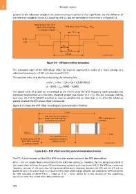
position of the reference sample in the downstream sync symbol of the superframe; see the definition of
the reference sample in clause 8.5.1 and Figure 8-12, and the definition of time event t1 in Figure 8-13.
Figure 8-9 – NTR phase offset estimation
The estimated value of the NTR phase offset (φ) shall be expressed in cycles of a clock running at a
reference frequency FS = 8 192 × fSC (see clause 10.4.2).
The obtained value of φ shall be coded using the following rule:
coded _ value ( floor A MOD() ) A
A 8192 f SC / 8000 52992
The coded value of φ shall be transmitted to the FTU-R using the NTR frequency synchronization eoc
command (represented as a two-byte unsigned integer (see clause 11.2.2.7)). The eoc message shall be
sent over the TPS-TC_MGMT interface as soon as possible but no later than 6 ms after the reference
sample at which the NTR phase offset is measured.
Figure 8-10 shows the NTR offset recording and communication timeline.
Figure 8-10 – NTR offset recording and communication timeline
The FTU-R shall reconstruct the 8 kHz NTR from the received values of the NTR phase offset.
NOTE – The FTU sample clock is proportional to the subcarrier spacing fSC. Therefore, the LTR, being proportional to
the sample clock, will have the same 50 ppm frequency variation as fSC (see clause 10.4.2). The NTR has a maximum
frequency variation of 32 ppm, thus the maximum difference in frequency between the NTR and the LTR will not
exceed 82 ppm. This would result in a maximum NTR phase offset change between two subsequent reference points
-6
for NTR recording of 8210 2TSF = 0.984 µs if TSF = 6 ms, where TSF is the duration of the superframe
(see clause 10.6). This is 0.8% of the 125 µs NTR period.
718