
Page 731 - 5G Basics - Core Network Aspects
P. 731
Transport aspects 2
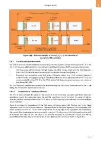
Figure 8-13 – Reference samples of events t1, t2, t3, t4 and a timeline of
eoc command transmission
8.5.2 ToD frequency synchronization
The ToD-O and ToD-R shall implement functionality with the objective of synchronizing the RTC-R to the
RTC-O in frequency, phase and time. Two methods are defined to achieve ToD frequency synchronization:
• ToD frequency synchronization through locking the PMD sample clock with the ToD frequency
(fmc): the FTU-R shall achieve frequency synchronization through loop timing, or
• Frequency synchronization using ToD phase difference values: the FTU-R achieves frequency
synchronization through processing of ToD phase difference values measured at the FTU-O and
communicated from the FTU-O to the FTU-R by the ToD frequency synchronization eoc command
(see clause 11.2.2.8).
The ToD frequency synchronization method is determined by the FTU-O and communicated to the FTU-R
during the initialization (see clause 12.3.4.2.3).
8.5.2.1 Computation of ToD phase difference
The FTU-O shall compute the value of using the RTC-O time base at every superframe with odd
superframe count. The computed value and the superframe count for which this value of was
recorded, shall be communicated to the FTU-R using the ToD frequency synchronization eoc command (see
clause 11.2.2.8).
Figure 8-14 shows the computation of the ToD phase difference value (). The top row in the figure
represents the 8 kHz RTC-O clock waveform. The second row in the figure represents the superframe clock
that is synchronous with the FTU-O's PMD sample clock; the rising edge of the superframe clock represents
the t1 event (the downstream reference sample crosses the U-O reference point) in the superframe shall
be recorded (see Figure 8-13). The value of shall be recorded in nanoseconds modulo 125 000 ns,
counted from the rising edge of the 8 kHz RTC-O clock down to the t1 event, as shown in Figure 8-14.
721