
Page 727 - 5G Basics - Core Network Aspects
P. 727
Transport aspects 2
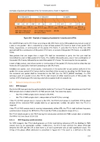
Examples of packet split between DTUs for transmission is shown in Figure 8-8.
Figure 8-8 – Example of mapping of packets for transmission in DTUs
The last DTU frame or the DTU frame preceding an idle DTU frame in the DTU payload may include a part of
a data or eoc packet – this is indicated by a start of data packet DTU frame or start of eoc packet DTU
frame, respectively, or continuation of the packet DTU frame. If used, the first frame of the next DTU
payload shall be a continuation of the packet DTU frame, or an end of the packet DTU frame, or an idle DTU
frame.
Data packets that are longer than a single DTU shall be transmitted in parts; the first part shall be
transmitted in a start of data packet DTU frame. This shall be followed by zero, one or more continuation of
the packet DTU frames, followed by an end of the packet DTU frame. The same applies for eoc packets.
A start of data packet, start of eoc packet or continuation of the packet DTU frame shall be either the last
frame of a DTU payload or the frame preceding an idle DTU frame.
Complete eoc packet, start of eoc packet, continuation of the packet (for an eoc packet) and end of the
packet (for an eoc packet) DTU frames shall be identified at the receiver by decoding the DTU frame type;
the recovered eoc packet shall be forwarded to the FME (via the TPS-TC_MGMT interface). If a DTU
carrying a part of a packet is lost, the TPS-TC shall discard all other received parts of this packet. The
number of DTU frames per DTU carrying a start of eoc packet shall not exceed one.
8.4 Network timing reference (NTR)
8.4.1 NTR transport
The 8-kHz NTR transport shall be performed after both the FTU-O and FTU-R reach showtime and the FTU-R
PMD sample clock is locked to the FTU-O PMD sample clock. Two cases may apply:
– the FTU-O PMD sample clock is locked to the NTR;
– the FTU-O PMD sample clock is independent of the NTR (free running).
If the FTU-O PMD sample clock is locked to the NTR, the FTU-R shall obtain its local 8-kHz NTR by direct
division of the recovered PMD sample clock by an appropriate number. No action from the FTU-O is
required.
If the FTU-O PMD sample clock is running independently of the NTR, the FTU-O shall facilitate frequency
synchronization between the NTR at the FTU-O and the FTU-R as described in clause 8.4.1.1.
The FTU-O shall indicate to the FTU-R during the initialization whether the PMD sample clock is locked to
the NTR or not (see clause 12.3.4.2.3).
8.4.1.1 NTR frequency synchronization
For NTR transport, the FTU-O shall generate an 8 kHz local timing reference (LTR) by dividing its PMD
sample clock by an appropriate number. Furthermore, the FTU-O shall estimate the phase offset (φ)
between the NTR and the LTR at time event t1 of each superframe with an odd superframe count. The
timing of the phase offset estimation is presented in Figure 8-9. Time event t1 is defined as the time
717