
Page 734 - 5G Basics - Core Network Aspects
P. 734
2 Transport aspects
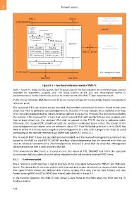
Figure 9-1 – Functional reference model of PMS-TC
NOTE – Figure 9-1 shows the DTU queue, the RTX queue and the RTX MUX between the α reference point and the
scrambler for explanatory purposes only. The actual position of the DTU and retransmission buffers in
implementations is vendor discretionary and can be at other points of the PMS-TC data transmission path.
In the receive direction, RMC frames and DTUs are recovered from the received data frames crossing the δ
reference point.
The recovered DTUs are de-interleaved, decoded, descrambled and checked for errors. Based on the error
check, the PMS-TC generates acknowledgements to the peer FTU that indicate DTUs received error free;
DTUs not acknowledged shall be retransmitted as defined in clause 9.8. Errored DTUs shall be discarded by
the receiver. If the received DTU is error free and all relevant DTUs with smaller SIDs are also received error
free or have timed out, the received DTU shall be passed to the TPS-TC via the α reference point.
Otherwise, the received DTU is buffered until the condition mentioned above is met. The format of the
acknowledgement and related rules are defined in clause 9.7. If the RX Enable primitive is set to RXoff, the
PMS-TC of the FTU-O may send a negative acknowledgement to a DTU with a proper error check to avoid
overloading of the receiver retransmission buffer (see clauses 8.1 and 8.1.1).
The recovered RMC frames are decoded and descrambled, and the received management parameters are
passed to the FME via the PMS-TC_MGMT interface. Acknowledgements that are received error free are
used to schedule retransmissions. Acknowledgements received in error shall be discarded. Management
data received error free is used to control the link.
If the downstream RMC frame is received in error, the values of TTR, TBUDGET and TA for the upstream
transmission shall stay identical to the values indicated in the last correctly received RMC frame.
9.1.1 δ reference point
The δ reference point describes a logical interface of the data plane between the PMS-TC and PMD sub-
layers. The data at the δ reference point in both transmit and receive directions is a stream of data frames.
Two types of data frames are defined: data frames carrying DTUs only (normal data frames) and data
frames carrying RMC and DTUs (RMC data frame), both defined in clause 9.5.
In the transmit direction, the PMS-TC shall deliver a data frame to the PMD when the PMD sets the TX
Enable primitive.
724