
Page 736 - 5G Basics - Core Network Aspects
P. 736
2 Transport aspects
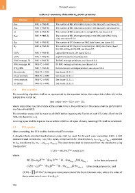
Table 9-2 – Summary of the PMS-TC_MGMT primitives
Primitive Direction Description
KFEC FME → PMS-TC The number of FEC information bytes in the data path, see clause 9.3.
RFEC FME → PMS-TC The number of FEC redundancy bytes in the data path, see clause 9.3.
Q FME → PMS-TC The number of FEC codewords in a single DTU, see clause 8.2.
KRMC FME → PMS-TC The number of FEC information bytes in the RMC path (RMC frame
size), see clause 9.6.3.
BDR FME → PMS-TC The number of DTU bytes in an RMC data frame, see clause 9.5.
BD FME → PMS-TC The number of DTU bytes in a normal (non-RMC) data frame, BDN in
the NOI and BDD in the DOI, see clause 9.5.
CNTLF FME → PMS-TC Logical frame count, see clause 10.5.1.
CNTSF FME → PMS-TC Superframe count, see clause 10.6.
RMC message, TX FME → PMS-TC TX RMC message primitives, see clause 9.6.4.
RMC message, RX PMS-TC → FME RX RMC message primitives, see clause 9.6.4.
RTX_CTRL FME → PMS-TC Retransmission control parameters, see clause 9.8.2.
fec anomaly PMS-TC → FME See clause 11.3.1.1.
rtx-uc anomaly PMS-TC → FME See clause 11.3.1.1.
rtx-tx anomaly PMS-TC → FME See clause 11.3.1.1.
lor defect PMS-TC → FME See clause 11.3.1.3.
9.2 DTU scrambler
The scrambling algorithm shall be as represented by the equation below; the output bit of data x(n) at the
sample time n shall be:
x(n) = m(n)+ x (n – 18) + x (n – 23),
where m(n) is the input bit of data at the sample time n. The arithmetic in this clause shall be performed in
the Galois Field GF(2).
The scrambler states shall be reset to all ONES before inputting the first bit of each DTU (the LSB of the SID
field, see clause 8.2.1.1).
Incoming bytes shall be input to the scrambler LSB first. All bytes of every incoming DTU shall be scrambled.
9.3 DTU encoder
After scrambling, the DTU shall be fed into the DTU encoder.
A standard byte-oriented Reed-Solomon code shall be used for forward error correction (FEC). A FEC
codeword shall contain NFEC = KFEC+RFEC bytes, comprised of RFEC check bytes c0, c1,...,c RFEC–2 , c RFEC–1 appended
to KFEC data bytes m0, m1, ...,m KFEC–2 , m KFEC–1 . The check bytes shall be computed from the data bytes using
the equation:
C (D ) M (D )D R FEC modG (D )
where:
M (D ) m 0 D K FEC 1 m 1 D K FEC 2 ...m K FEC 2 D m K FEC 1 is the data polynomial,
C (D ) Dc 0 R FEC 1 Dc 1 R FEC 2 ...c R FEC 2 D c R FEC is the check polynomial , and
1
i
G (D ) (D ) is the generator polynomial of the Reed-Solomon code, where the index of
the product runs from i= 0 to RFEC-1.
726