
Page 735 - 5G Basics - Core Network Aspects
P. 735
Transport aspects 2
In the receive direction, the PMS-TC shall accept a data frame when the PMD sets the RX Enable primitive.
The timing of data frame transfers to and from the PMD is determined by the TX and RX clock sourced by
the PMD: each transferred data frame is associated with a particular transmitted symbol or a particular
received symbol, respectively (RMC symbol, data symbol, idle symbol or quiet symbol, as defined in clause
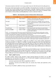
10.5). The flow control primitives describing data frame transfer are shown in Table 9-1.
Table 9-1 – Data frame flow control primitives at the δ reference point
Primitive Direction Description
TX Enable (TX Data Req) PMD PMS-TC Primitive indicating that the PMD is requesting to receive
the data frame from the PMS-TC (Note 1)
RX Enable PMD PMS-TC Primitive indicating that a valid data frame (normal data
frame or RMC data frame) is ready at the PMD for transfer
to the PMS-TC
TX RMC PMD PMS-TC Primitive indicating the RMC symbol position (start of the
logical frame)
TX and RX clock PMD PMS-TC Data frame transfer clock reference (symbol timing)
Data frame disabled PMS-TC PMD Primitive indicating that an idle data frame is transferred
by the PMS-TC (Note 2)
NOTE 1 – The TX Enable primitive shall only be turned off during the data frames associated with symbol position on which
transmission is not allowed: those are TA symbol positions, symbol positions exceeding the allocated TBUDGET, sync symbol
positions, and symbol positions assigned for opposite direction of transmission.
NOTE 2 – Idle data frame is a normal data frame which contains only dummy DTUs; it is sent if no data is available for
transmission and may be removed by the PMD; on the symbol positions indicated by the data frame disabled primitive, the PMD
may transmit either a data symbol, an idle symbol or a quiet symbol, using the rules described in clause 10.7 (limiting the index
of the last data symbol that can be utilized for transmission to ETT), or a pilot symbol, using the rules defined in clause 10.4.5.1.
During the showtime, one data frame is pulled from the PMS-TC every symbol position dedicated for
transmission (see NOTE 1 in Table 9-1). The PMS-TC identifies the type of the data frame (RMC data frame
or normal data frame) and also whether the normal data frame is for the normal operation interval (NOI) or
for the discontinuous operation interval (DOI) based on the TX RMC primitive and the values of parameters
TTR and TA (see clause 10.7), respectively. The size of these frames may be different (due to different bit
loading in the corresponding symbols).
In the transmit direction, data frames shall be sent across the δ reference point in the same order as the
packets encapsulated into the DTUs of these data frames are entering the TPS-TC across the γ reference
point (DTUs to be retransmitted are sent prior to new DTUs – see clause 9.8). In the receive direction, data
frames shall be sent across the δ reference point in the order that they are recovered by the PMD.
9.1.2 PMS-TC_MGMT interface
The PMS-TC_MGMT reference point describes a logical interface between the PMS-TC and the FME
(see Figure 9-1). The interface is defined by a set of control and management parameters (primitives).
These parameters are divided into two groups:
– parameters generated by the FME and applied to the PMS-TC;
– parameters retrieved by the PMS-TC from the received data frames and submitted to the
PMS-TC ME.
The summary of the PMS-TC_MGMT primitives is presented in Table 9-2.
725