
Page 94 - Kaleidoscope Academic Conference Proceedings 2024
P. 94
2024 ITU Kaleidoscope Academic Conference
in jeans, which is easily obtained in day-to-day activities. By cutting down on back radiation, the EBG structure helps
The thickness of the copper utilized for the ground and the antenna achieve a higher realized gain. The floquet port
radiator is 0.7 mm. The antenna feed measures 3 mm in is used to create and simulate the unit cell structure in the
width and 12 mm in length, and it is a 50 Ω microstrip feed. CST MS tool. This EBG unit cell has a bandwidth of 3.5 to
The proposed antenna has three layers: There is a 4 x 4 3.6 GHz, which is either side of the center frequency at
0
EBG array that acts as a reflector surface on the bottom, a 3.53 GHz within the range of ±90 . So, it is clear that the
flexible, thin foam layer with 1 mm thick positioned proposed structure is capable of operating within the
between EBG array, and wearable antenna, which is desired Sub-6 GHz band of IoT applications.
developed as a ring on top. The foam layer's function is to
prevent contact between the edge of the antenna and the
EBG surface. Firstly, the usual equation provided in [23] is
used to calculate the radii R1 of the circular patch. The
circular patch antenna's initial four modes include 110 ,
210 , 010 , and 310 . The 110 , is the dominant
mode, and its resonant frequency is determined by
( ) = 1.8421 0 (1)
2π 1√
In free space, the speed of light is represented as 0 .
Fringing is taken into consideration while calculating the
circular patch's radius R1, and the resultant effective radius
R1e is given by
1 ⁄
2ℎ π 1 2
1 = {1 + [ ( ) + 1.7726]} (2)
1
π 1 2ℎ
Equation (2) is then used to modify the resonance
frequency for the dominant mode 110 which is thus
given as
( ) = 1.8421 0 (3)
2π 1 √
At first, consider the resonant frequency f = 3.5 GHz and
r
calculate the radius R1, which is 11.5 mm. In the design
procedure, first design a circular patch with a radius R1 =
11.5 mm, L = 66.80 mm, W = 66.80 mm and Lf = 14 mm.
Antenna 1 represents circular patch antenna. Antenna 2 is
designed as a circular patch antenna with a particular
modification. The patch is then cut into a ring with an 8.5
mm radius, and a section of the ground plane is used. This
adaptation is known as Antenna 2. Additionally, Antenna 3
is the C-shaped stub that is put across the circular patch and
the feed line. Finally, a 4 ×4 EBG array is backed to get the
final design. Figure 2 shows the various stages of the
designed antenna's evaluation. The overall dimension of the
proposed antenna with an EBG-backed reflector is 66.80 x
66.80 x 0.7 mm3, which is proposed for IoT applications.
The CST tool is used for simulation and implementation.
All the optimization parameters are illustrated in figure 1.
2.2 EBG designs
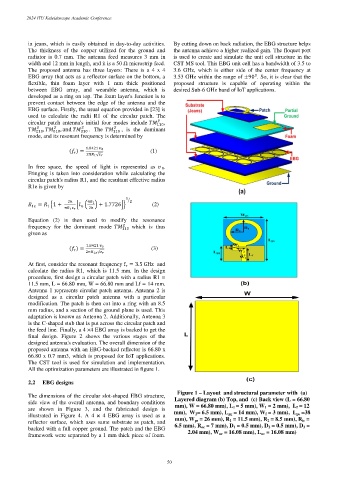
Figure 1 – Layout and structural parameter with (a)
The dimensions of the circular slot-shaped EBG structure,
side view of the overall antenna, and boundary conditions Layered diagram (b) Top, and (c) Back view (L = 66.80
mm), W = 66.80 mm), L 1 = 5 mm), W 1 = 2 mm), L f = 12
are shown in Figure 3, and the fabricated design is
illustrated in Figure 4. A 4 × 4 EBG array is used as a mm), W 2 = 6.5 mm), L pg = 14 mm), W f = 3 mm), L ps =38
mm), W ps = 26 mm), R 1 = 11.5 mm), R 2 = 8.5 mm), R ic =
reflector surface, which uses same substrate as patch, and
backed with a full copper ground. The patch and the EBG 6.5 mm), R oc = 7 mm), D 1 = 0.5 mm), D 2 = 0.5 mm), D 3 =
2.04 mm), W uc = 16.08 mm), L uc = 16.08 mm)
framework were separated by a 1 mm thick piece of foam.
– 50 –