
Page 789 - 5G Basics - Core Network Aspects
P. 789
Transport aspects 2
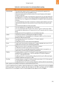
Table 10-9 – Control parameters for vectoring feedback reporting
Parameter name Definition
Vectored bands The downstream frequency bands for which the FTU-R shall send VF samples for the
subcarriers through the vectoring feedback channel.
The vectored bands shall be defined by indices of the lowest frequency and the highest
frequency subcarriers.
N_band denotes the number of vectored bands configured. No more than eight bands shall
be configured (i.e., N_band ≤ 8). The configured bands shall be identified by their numbers:
vb = 0, 1, 2, 3, 4, 5, 6, 7 assigned in the ascending order of subcarrier indices associated with
the band.
N_carrier(vb) denotes the number of subcarriers in frequency band number vb, and can be
computed as the index of the stop subcarrier minus the index of the start subcarrier plus
one.
The vectored bands shall not overlap one another.
F_sub The sub-sampling factor to be applied to the vectored bands.
For every vectored band, the VF sample of the subcarrier with the smallest index shall be
th
transmitted first, followed by the VF sample of every F_sub subcarrier within the vectored
band.
Configured by the VCE and applied for each vectored band separately.
F_block The block size (number of subcarriers) for grouping of VF samples.
Configured by the VCE. The same block size configuration shall be used for all vectored
bands (see Tables 10-10 and 11-41).
B_min Lower bound of the bit index for reporting of a VF sample component
(see clause 10.3.2.3.2).
Configured by the VCE for each vectored band separately.
B_max Upper bound of the bit index for reporting of a VF sample component (see clause 10.3.2.1).
Configured by the VCE for each vectored band separately.
L_w Maximum number of bits for reporting of a VF sample component.
Configured by the VCE for each vectored band separately.
If L_w is set to zero for a particular vectored band, that band shall not be reported. L_w
shall be set to a non-zero value for at least one vectored band.
Padding Indicates whether or not the FTU-R shall pad VF samples through sign extension or zero
padding (Note) to maintain using L_w bits for reporting of a VF sample component if
S < L_w – 1 (see clause 10.3.2.3.2).
Configured by the VCE. The same padding configuration shall be used in all vectored bands.
Padding is enabled by setting this bit to ONE.
Rounding Indicates whether or not the FTU-R shall round half-up (see clause 10.3.2.3.2) the reported
VF sample based on the MSB that is not reported.
Configured by the VCE. The same rounding configuration shall be used in all vectored bands.
NOTE – Selection of zero padding or sign extension is vendor discretionary by the FTU-R
In case of reporting of error samples, Table 10-10 defines the mandatory values for the vectoring feedback
control parameters. In particular, it defines the valid values for the VCE to configure and the mandatory
values for the FTU-R to support. The FTU-O shall support all valid values for VCE to configure.
779