
Page 786 - 5G Basics - Core Network Aspects
P. 786
2 Transport aspects
cancellation precoders per vectored subcarrier of size NN. Knowing the transmit symbols on each
disturbing channel, the precoder precompensates the actual transmit symbol such that at the far-end
receiver input, the crosstalk is significantly reduced. As a part of the channel matrix or separately, the VCE
shall set the precoder such that the precoder output signals (Z' values shown in Figure 10-16) shall not lead
at the U reference point to violation of the PSD limit corresponding with the tssi (see clause 10.2.1.5.3).
The channel matrix and the resulting FEXT cancellation precoder matrix are assumed to be entirely
managed inside the DPU. An information exchange between the FTU-O and FTU-R is required in each
vectored line to learn, track and maintain the channel matrix and associated FEXT cancellation precoder
matrix (see vectoring feedback channel definition in clause 10.3.2 and initialization in clause 12.3). The
actual algorithms for processing this information to obtain the channel matrix and to generate the FEXT
cancellation precoder are vendor discretionary. Depending on the implementation, it may be possible for
the VCE to directly determine the FEXT cancellation precoder matrix and only have an implicit learning of
the channel matrix.
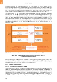
NOTE – Symbol encoder represents the data, sync, pilot or initialization symbol encoder shown in Figure 10-1.
Figure 10-16 – Vectored group functional model of PMD sub-layer using N×N
precoder for downstream vectoring
An FTU-O shall support FEXT cancellation precoding, as shown in Figure 10-1 and Figure 10-16. At its own
discretion, the VCE may apply to sync symbols precoding coefficients that are different (including any
diagonal precoder matrix) from those used for other symbol positions.
10.3.2 Vectoring feedback channel
10.3.2.1 Definition of normalized error sample
The FTU-R converts the received time domain signal into frequency domain samples, resulting in a complex
value Z for each of the received subcarriers. The subsequent constellation de-mapper associates each of
these complex values Z with a particular constellation point, represented by a value C. Figure 10-17 shows
the computation of a normalized error sample E for a particular subcarrier in a particular sync symbol. The
normalized error sample represents the error between the received complex data sample Z normalized to
the 4-QAM constellation and the corresponding expected constellation point C, referred to the input of the
776