
Page 784 - 5G Basics - Core Network Aspects
P. 784
2 Transport aspects
it starts at the beginning of the first downstream logical frame of the second superframe after transmission
of O-P-SYNCHRO 1-1). During an initialization stage with IDS active, IDS shall be applied over all
downstream SOC symbols located at or after the IDS was started or restarted.
The first bit of the IDS shall be applied to the first SOC symbol located at or after the position where the IDS
is started or restarted, the second bit to the next SOC symbol, etc., until the end of the IDS. When the last
bit of the IDS is applied, the next bit shall be again the first bit of the IDS. After starting or restarting, the IDS
shall be repeated periodically until the end of the following O-P-SYNCHRO signal. The last repetition of the
IDS may be incomplete.
NOTE – Sync symbols and quiet symbols are not modulated by IDS. The IDS is not advanced on sync symbol and quiet
symbol positions.
10.2.2.2.3 SOC symbol repetition
To increase the robustness of the downstream SOC, each downstream SOC symbol, except those contained
in O-P-SYNCHRO signals, may be repeated to form a group of consecutive identical SOC symbols. The SOC
symbols shall be repeated before the IDS is applied to them. The number of repetitions in a group is
selected during the ITU-T G.994.1 handshake phase. When SOC symbol repetition is applied, the SOC
symbol repetition shall be started or restarted at the same time as the IDS is started or restarted,
respectively. When the SOC symbol repetition is started or restarted, the first transmitted SOC symbol shall
be the first element of the group of identical symbols. The last group of identical symbols before an
O-P-SYNCHRO signal may be incomplete.
10.2.2.3 Pilot symbol encoder
All pilot tone subcarriers of the pilot symbol shall be modulated by bits 00 using the 2-bit constellation
mapping defined in clause 10.2.1.4. For all other subcarriers, the values of Xi and Yi shall be set to zero (Zi =
0).
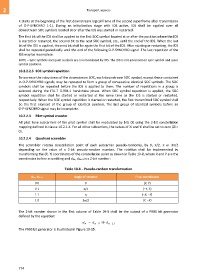
10.2.2.4 Quadrant scrambler
The scrambler rotates constellation point of each subcarrier pseudo-randomly, by 0, /2, or 3/2
depending on the value of a 2-bit pseudo-random number. The rotation shall be implemented by
transforming the (X, Y) coordinates of the constellation point as shown in Table 10-8, where X and Y are the
coordinates before scrambling and d2n, d2n+1 is a 2-bit number:
Table 10-8 – Pseudo-random transformation
d2n, d2n+1 Angle of rotation Final coordinates
0 0 0 (X, Y)
0 1 /2 (−Y, X)
1 1 (−X, −Y)
1 0 3/2 (Y, −X)
The 2-bit number shown in the first column of Table 10-8 shall be the output of a PRBS bit generator
defined by the equation:
d d d
n n 9 n 11
The PRBS bit generator is illustrated in Figure 10-15.
774