
Page 787 - 5G Basics - Core Network Aspects
P. 787
Transport aspects 2
quadrant descrambler. This expected constellation point corresponds to the constellation point obtained
after the quadrant scrambler and before the constellation point scaling in the generation of the sync
symbol at the FTU-O (see clauses 10.2.2.2 and 10.2.1.5).
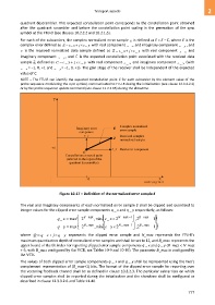
For each of the subcarriers, the complex normalized error sample E is defined as E = Z C, where E is the
complex error defined as E e_ x j e_ y with real component e _ and imaginary component e _ , and
y
x
Z is the received normalized data sample defined as Z z _ x j z _ y with real component z _ x and
imaginary component z _ y , and C is the expected constellation point associated with the received data
sample Z, defined as C c _ x j c _ y with real component c _ x and imaginary component c _ y (with
c _ x = −1, 0, +1 and c _ y = −1, 0, +1). The gain stage of the receiver shall be independent of the expected
value of C.
NOTE – The FTU-R can identify the expected constellation point C for each subcarrier by the element value of the
probe sequence modulating the sync symbol, communicated to FTU-R during the initialization (see clause 12.3.3.2.1)
or by the probe sequence update command (see clause 11.2.2.15) during the showtime.
Figure 10-17 – Definition of the normalized error sample E
The real and imaginary components of each normalized error sample E shall be clipped and quantized to
integer values for the clipped error sample components q _ x and q _ y respectively, as follows:
q _ x max 2 B _ max , min _ xe 2 N _ max 1 2 , B _ max 1
q _ y max 2 B _ max , min _ ye 2 N _ max 1 2 , B _ max 1
where Q q _ x j q _ y represents the clipped error sample and N_max represents the FTU-R's
maximum quantization depth of normalized error samples and shall be set to 12, and B_max represents the
upper bound of the bit index for reporting clipped error sample components q _ x and q _ y (B_max < N_max
+ 6, with B_max configured by the VCE, see Tables 10-9 and 10-10). The parameter B_max is configured by
the VCE.
The values of both clipped error sample components q _ x and q _ y shall be represented using the two's
complement representation of (B_max+1) bits. The format of the clipped error sample for reporting over
the vectoring feedback channel shall be as defined in clause 10.3.2.3. The particular subcarriers on which
clipped error samples shall be reported during the initialization and the showtime shall be configured as
described in clause 12.3.3.2.6 and Table 11-40.
777