Page 794 - 5G Basics - Core Network Aspects
P. 794
2 Transport aspects
10.3.2.3.2.3 Calculation of N_block
This clause applies to both reporting of DFT output samples and reporting of error samples.
For the assigned value of F_block, the block consists of VF samples reported for F_block subsequent
subcarriers from those assigned for reporting in the vectored band. The subcarriers shall be assigned to
blocks starting from the lowest frequency subcarrier of the vectored band, subsequently, in ascending
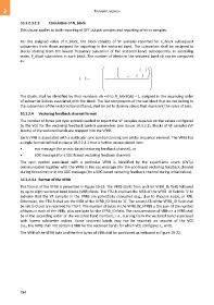
order, F_block subcarriers in each block. The number of blocks in the vectored band vb can be computed
as:
N _ carrier( vb)
ceiling
N _ block( vb) ceiling F _ sub( vb)
F _ block
The blocks shall be identified by their numbers: eb = 0 to N_block(vb) – 1, assigned in the ascending order
of subcarrier indices associated with the block. The last components of the last block that do not belong to
the subcarriers of the vectored band (if any), shall be set to dummy values that represent the value of zero.
10.3.2.4 Vectoring feedback channel format
The number of bytes per sync symbol needed to report the VF samples depends on the values configured
by the VCE for the vectoring feedback control parameters (see clause 10.3.3.2). Blocks of VF samples (VF
blocks) of the vectored bands are mapped into the VFRB.
Each VFRB is associated with a particular sync symbol carrying one probe sequence element. The VFRB has
a single format defined in clause 10.3.2.4.1 that is further encapsulated into:
• eoc message (for an eoc-based vectoring feedback channel), or
• SOC message (for a SOC-based vectoring feedback channel).
The sync symbol associated with a particular VFRB is identified by the superframe count (CNTSF)
communicated together with the VFRB in the eoc message (for the eoc-based vectoring feedback channel
during showtime) or in the SOC message (for a SOC-based vectoring feedback channel during initialization).
10.3.2.4.1 Format of the VFRB
The format of the VFRB is presented in Figure 10-22. The VFRB starts from an 8-bit VFRB_ID field, followed
by up to eight vectored band blocks (VBB) fields. The FTU-R shall set the MSB of the VFRB_ID field to '1' to
indicate that the VF samples in the VFRB are potentially corrupted (e.g., due to impulse noise, or RFI).
Otherwise, the FTU-R shall set the MSB of the VFRB_ID field to '0'. The seven LSB of the VFRB_ID field shall
be set to 0 and are reserved for ITU-T. The number of bytes in the VFRB (N_VFRB) is the sum of the number
of bytes in each of the VBBs, plus one byte for the VFRB_ID field. The concatenation of VBBs in a VFRB shall
be in the ascending order of the vectored band numbers, i.e., starting from the vectored band associated
with lowest subcarrier indices. Some vectored bands may not be reported on request of the VCE
(i.e., the VFRB shall not contain a VBB for the vectored bands for which VCE configures L_w=0).
The MSB of the VFRB byte and the first bytes of VBB shall be positioned as indicated in Figure 10-22.
784

