
Page 785 - 5G Basics - Core Network Aspects
P. 785
Transport aspects 2
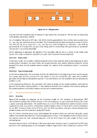
Figure 10-15 – Bit generator
Two bits from the scrambler shall be mapped to each subcarrier, including DC. The two bits corresponding
to DC shall be overwritten with 00.
For a modulator that uses an IDFT size = 2N, 2N bits shall be generated by the scrambler every symbol (b0 b1
b2 ... b2N−2 b2N−1) in each transmission direction. The first two bits (b0 b1) shall correspond to subcarrier 0, the
next two bits (b2 b3) to subcarrier 1, etc.; bits (b2i b2i+1) shall correspond to subcarrier i. Bits shall be
generated for all N subcarriers, not just those being used for transmission. Bits generated for subcarriers
that are not in use shall be discarded.
At the beginning of operation, all registers of the scrambler shall be set to a certain 11-bit initial value
(seed). Two modes of scrambler operation are used: reset mode and free-running mode.
10.2.2.4.1 Reset mode
In the reset mode, the scrambler shall be initialized (reset to the required seed) at the beginning of every
symbol period. Therefore, the same 2N bits will be generated for each symbol, and each subcarrier will be
assigned the same two-bit pseudo-random number for rotation of its constellation point in successive
symbols.
10.2.2.4.2 Free-running mode
In the free-running mode, the scrambler shall not be reinitialized at the beginning of each symbol period,
but instead shall continue running from one symbol to the next. Practically, this means the scrambler
generates 2N bits that are allocated to symbol s. The next 2N bits from the scrambler are then allocated to
symbol s+1, etc.
In the downstream direction, the scrambler shall advance during all Mds symbol positions and shall not
advance during other symbol positions. In the upstream direction, the scrambler shall advance during all
Mus symbol positions and shall not advance during other symbol positions.
10.3 Precoder (downstream vectoring)
10.3.1 Overview
Figure 10-16 provides an overview of the functional model for the inclusion of downstream FEXT
cancellation precoding at the DPU for all lines in the vectored group, as a generalization of Figure 10-1 from
a signal processing perspective. The model shows an array of the downstream symbol encoders (which
represent the data, sync, pilot or initialization symbol encoders shown in Figure 10-1) and the modulation
by the IDFT functional blocks of the FTU-Os, with the FEXT cancellation precoder inserted between the
symbol encoders and the modulation by the IDFT blocks.
The VCE of the vectored group learns and manages the channel matrix per vectored subcarrier, which
reflects the channel characteristics of the managed group of lines. In the functional model in Figure 10-16,
the channel matrix for each vectored subcarrier is of size NN where N is the number of lines in the
vectored group.
From the channel matrix, a VCE derives a FEXT precoder matrix, which is used to compensate the FEXT from
each line in the vectored group. In the functional model in Figure 10-16, this is shown by a matrix of FEXT
775