
Page 788 - 5G Basics - Core Network Aspects
P. 788
2 Transport aspects
10.3.2.2 Definition of DFT output samples
The FTU-R shall support reporting of DFT output samples referred to the U-R reference point (Fk) for sync
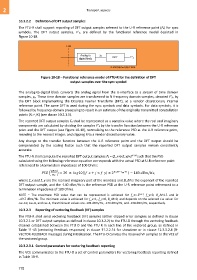
symbols. The DFT output samples, F’k, are defined by the functional reference model depicted in
Figure 10-18.
U-R
Analog to y k
digital block DFT F' k
G.9701(14)-Cor.1(15)_F10-18
Figure 10-18 – Functional reference model of FTU-R for the definition of DFT
output samples over the sync symbol
The analog-to-digital block converts the analog signal from the U-interface to a stream of time domain
samples, yn. These time domain samples are transformed to N frequency domain samples, denoted F’k, by
the DFT block implementing the Discrete Fourier Transform (DFT), at a vendor discretionary internal
reference point. The same DFT is used during the sync symbols and data symbols. For data symbols, it is
followed by frequency domain processing to result in an estimate of the originally transmitted constellation
points (Xi + jYi) (see clause 10.2.1.5).
The reported DFT output samples Fk shall be represented as a complex value where the real and imaginary
components are calculated by dividing the samples F’k by the transfer function between the U-R reference
point and the DFT output (see Figure 10-18), normalizing to the reference PSD at the U-R reference point,
rounding to the nearest integer, and clipping it to a vendor discretionary value.
Any change to the transfer function between the U-R reference point and the DFT output should be
compensated by the scaling factor such that the reported DFT output samples remain consistently
accurate.
The FTU-R shall compute the reported DFT output samples Fk = (f_x+j×f_y)×2 B_M such that the PSD
calculated using the following reference equation corresponds with the actual PSD at U-R reference point
referenced to a termination impedance of 100 Ohms:
( ) = 20 × 10(| _ + × _ | × 2 _ − +1 ) − 140 / ,
where f_x and f_y are the real and imaginary part of the mantissa and B_M is the exponent of the reported
DFT output sample, and the -140 dBm/Hz is the reference PSD at the U-R reference point referenced to a
termination impedance of 100 Ohms.
NOTE – The maximum PSD value that can be represented is achieved for f_x=-2 Lw-1 , f_y=0, B_M=15 and is
–49.7 dBm/Hz. The minimum value is achieved for f_x=1, f_y=0, B_M=0, and depends on the selected Lw value: for
Lw=10, Lw=6, and Lw=4, the minimum values are -194 dBm/Hz, -170 dBm/Hz, and -158 dBm/Hz, respectively.
10.3.2.3 Reporting of vectoring feedback (VF) samples
The FTU-R shall send vectoring feedback (VF) samples (either clipped error samples as defined in clause
10.3.2.1 or DFT output samples as defined in clause 10.3.2.2) to the FTU-O through the vectoring feedback
channel established between the FTU-O and the FTU-R in each line of the vectored group, as defined in
Table 11-43 (vectoring feedback responses) in clause 11.2.2.14 for showtime or in clause 12.3.3.2.8 (R-
VECTOR-FEEDBACK message) during initialization. The FTU-O conveys the received VF samples to the VCE of
the vectored group.
10.3.2.3.1 Control parameters for vectoring feedback reporting
The VCE communicates to the FTU-O a set of control parameters for vectoring feedback reporting defined
in Table 10-9.
778