
Page 739 - 5G Basics - Core Network Aspects
P. 739
Transport aspects 2
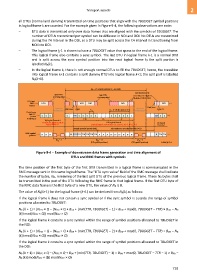
all DTUs (normal and dummy) transmitted on time positions that align with the TBUDGET symbol positions
in logical frame k are counted. For the example given in Figure 9-4, the following observations are note:
– DTU data is transmitted only over data frames that are aligned with the symbols of TBUDGET. The
number of DTUs transmitted per symbol can be different in NOI and DOI. No DTUs are transmitted
during the TA interval in the DOI, so a DTU may be split across the TA interval in transitioning from
NOI into DOI.
– The logical frame k-1 is shown to have a TBUDGET value that spans to the end of the logical frame.
This logical frame also contains a sync symbol. The last DTU in logical frame k-1 is a normal DTU
and is split across the sync symbol position into the next logical frame k; the split portion is
labelled NB(k).
– In the logical frame k, there is not enough normal DTUs to fill the TBUDGET; hence, the transition
into logical frame k+1 contains a split dummy DTU into logical frame k+1; the split part is labelled
NB(k+1).
M = 23 symbol positions (T seconds)
F F
Split ummy DTU:d
Split DTU Split DTU ( +1)k
(carrying data) (carrying data) count bytes for N B
in span of TBUDGET
DTU and
RMC . .. DTU DTU DTU DTU DTU . ..
frames
RMC atad
Upstream RMC atad N k( ) Upstream N k( +1)
transmission B T S B = B (#idle symb.in B )'– ' transmission B
Data ramesf
PMS-TC . .. rmc rmc . ..
(across d d d d d d d d d d d d d d i d d
δ interface) TTR TA B'
DS ogical rame 1l f – k
TBUDGET spans to end of DS ogical rame l f k DS ogicall
logical frame 1k– Logical rame : TBUDGET=12. TTR=6, TA=3, B=6, B=5f k ' frame +1
k
Normal peration nterval (NOI)o i Discontinuous peration nterval (DOI)o i
PMD ymbol s . .. . ..
positions B' B' B' . .. SS TTR TTR TTR TTR TTR TTR A A A B' B' B' B' B' B' . .. R TTR TTR
M = 5 M = 17 M = 5
us ds us
(DS symbol positions) (US symbol positions) G.9701(14)_F9-4
Figure 9-4 – Example of downstream data frame generation and time alignment of
DTUs and RMC frames with symbols
The time position of the first byte of the first DTU transmitted in a logical frame is communicated in the
RMC message sent in this same logical frame. The "DTU sync value" field of the RMC message shall indicate
the number of bytes, NB, remaining of the last split DTU of the previous logical frame. These NB bytes shall
be transmitted in the part of the DTU following the RMC frame in that logical frame. If the first DTU byte of
the RMC data frame is the first byte of a new DTU, the value of NB is 0.
The value of NB(k+1) for the logical frame (k+1) can be derived from NB(k) as follows:
If the logical frame k does not contain a sync symbol or if the sync symbol is outside the range of symbol
positions allocated to TBUDGET:
NB (k + 1) = (NFEC × Q – (NFEC × Q + BDR + (min(TTR, TBUDGET) – 1) × BDN + max(0, TBUDGET – TTR) × BDD – NB
(k)) mod(NFEC × Q)) mod(NFEC × Q)
If the logical frame k contains a sync symbol within the range of symbol positions allocated to TBUDGET in
the NOI:
NB (k + 1) = (NFEC × Q – (NFEC × Q + BDR + (min(TTR, TBUDGET) – 2) × BDN + max(0, TBUDGET – TTR) × BDD – NB
(k)) mod(NFEC × Q)) mod(NFEC × Q)
If the logical frame k contains a sync symbol within the range of symbol positions allocated to TBUDGET in
the DOI:
NB (k + 1) = (NFEC × Q – (NFEC × Q + BDR + (min(TTR, TBUDGET) – 1) × BDN + max(0, TBUDGET – TTR − 1) × BDD –
NB (k)) mod(NFEC × Q)) mod(NFEC × Q)
729