
Page 741 - 5G Basics - Core Network Aspects
P. 741
Transport aspects 2
Incoming RMC bytes shall be input to the scrambler LSB first; the LSB of the first byte corresponds to time
sample n = 1. All KRMC bytes of the RMC frame (RMC message and pad) shall be scrambled.
9.6.3 RMC encoder
After scrambling, the RMC shall be protected by a Reed-Solomon FEC code using the same polynomial as
that used for DTU encoding defined in clause 9.3. However, for the purpose of RMC encoding, parameters
NFEC, KFEC and RFEC are referred to as NRMC, KRMC and RRMC, and the valid values of these parameters shall be as
specified in this clause.
The encoder RS(NRMC, KRMC) shall insert RRMC = 16 redundancy bytes after KRMC data bytes, counting from the
first byte of the RMC frame. The RMC frame size after FEC encoding shall be NRMC = KRMC+16 bytes.
The number of data bytes KRMC allocated for an RMC frame shall be set during the initialization
(see clause 12.3.4.2.5) and shall not be changed during the showtime. The range of valid values for KRMC
shall be from 32 to 64.
NOTE – The defined valid combinations of FEC parameters [KRMC, NRMC] provide error detection capability equivalent to
or higher than a 32-bit CRC.
9.6.4 RMC message fields
Each RMC message shall be transmitted over one RMC symbol.
An RMC message comprises a number of different commands. The size of each command (see Table 9.2 to
Table 9.9) shall be an integer number of bytes. Different sets of commands may be sent over different RMC
messages.
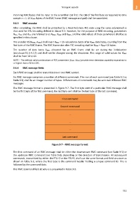
The RMC message format is presented in Figure 9-7. The first byte sent of a particular RMC message shall
be the first byte of the first command; the last byte sent shall be the last byte of the last command.
First command
Second command
…
…
…
Last command
Figure 9-7 – RMC message format
The first command of an RMC message shall be either the downstream RMC command (see Table 9-5) or
the upstream RMC command (see Table 9-8), depending on the direction of transmission. All subsequent
commands, transmitted by either the FTU-O or the FTU-R, shall use the same format and field structure as
shown in Table 9-3, where the first byte is the command header holding a unique command ID. This is
followed by the command data.
The RMC command field structure is presented in Table 9-3.
731