Page 743 - 5G Basics - Core Network Aspects
P. 743

Transport aspects                                              2


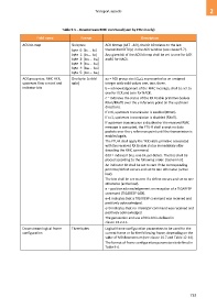
                                   Table 9-5 – Downstream RMC command (sent by FTU-O only)
                     Field name              Format                           Description

             ACK bit-map                Six bytes:         ACK bitmap [b47 ...b0], the bit b0 relates to the last
                                        byte  0: [b7 ... b0]   transmitted DTU(s) in the ACK window (see clause 9.7).
                                        byte  1: [b15... b8]   Any given bit of the ACK bitmap shall be set to one for ACK
                                        byte  2: [b23 ... b16]   and 0 for NACK.
                                        byte  3: [b31 ... b24]
                                        byte  4: [b39 ... b32]
                                        byte  5: [b47 ... b40]
             ACK group size, RMC ACK,   One byte: [e ddd   aa = ACK group size (Gack), represented as an unsigned
             upstream flow control and   aabc]             integer with valid values one, two, three.
             indicator bits                                b = acknowledgement of the RMC message; shall be set to
                                                           one for ACK and zero for NACK.
                                                           c = indicates the status of the RX Enable primitive (values
                                                           RXon/RXoff) over the γ reference point (in the upstream
                                                           direction).
                                                           If c=0, upstream transmission is enabled (RXon).
                                                           If c=1, upstream transmission is disabled (RXoff).
                                                           If upstream transmission is disabled or the received RMC
                                                           message is corrupted, the FTU-R shall accept no data
                                                           packets over the γ reference point until the transmission is
                                                           enabled again.
                                                           The FTU-R shall apply the TX Enable primitive associated
                                                           with the received RX Enable status immediately after
                                                           decoding the RMC command.
                                                           ddd = indicator bits, one bit per defect. The bits shall be
                                                           placed according to the following order: [los lom lor].
                                                           An indicator bit shall be set to zero if the corresponding
                                                           primitive/defect occurs and set to one otherwise (active
                                                           low).
                                                           The bits shall be set to zero if a defect occurs and set to one
                                                           otherwise (active low).
                                                           e = positive acknowledgement on reception of a TIGARESP
                                                           command (TIGARESP-ACK).
                                                           e=1 indicates that a TIGARESP command was received and
                                                           positively acknowledged.
                                                           e=0 indicates that no TIGARESP command was received and
                                                           positively acknowledged.
                                                           The generation and use of this bit is defined in
                                                           clause 13.2.2.1.

             Downstream logical frame   Three bytes        Logical frame configuration parameters to be used for the
             configuration                                 current frame or for the following frame, depending on the
                                                           value of MB downstream (see clause 10.7 and Table 12-44).
                                                           The format of frame configuration parameters is defined in
                                                           Table 9-6.


                                                                                                         733
   738   739   740   741   742   743   744   745   746   747   748