
Page 79 - Kaleidoscope Academic Conference Proceedings 2024
P. 79
Innovation and Digital Transformation for a Sustainable World
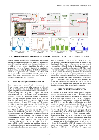
Fig. 3 Schematic of seamless fiber–wireless bridge system. CS: central station; RAU: remote radio head; Rx: receiver.
flexible solution for generating radio signals. The antenna speed O/E converter for conversion into a radio signal in the
site can be significantly simplified using this method. An low-frequency band. The frequency of the down-converted
optical heterodyne method using free-running lasers can signal equals the frequency difference between the LO and
provide ultrawide frequency tunability for radio signal the modulated sideband. Similar to the signal generation, a
generation. However, frequency instability is significantly free-running laser can be used as an optical LO for signal
high, resulting in large frequency fluctuations and phase downconversion. However, random wavelength fluctuations
noise in the generated radio signals. An optical self- of lasers increase the frequency instability and phase noise
heterodyne method using stabilized optical signals from a of the generated signals. Frequency-stabilized two-tone
single laser source can generate radio signals with high optical signal generation, shown in Fig. 2(d), using an optical
frequency stability and low phase noise. signal from a single light source is appropriate for photonic
up- and down-conversion. In the following sections, we
2.2 Radio signal reception and down-conversion present fiber–wireless systems that use photonic up- and
down-conversion methods with stabilized two-tone optical
Radio signals can be received and down-converted to a signal generation for different application scenarios.
lower-frequency band using either electrical or photonic
methods. Using the electrical method, shown in Fig. 2(a), the 3. FIBER–WIRELESS BRIDGE SYSTEM
signal is input to an electric mixer for downconversion to a
lower-frequency band using an LO signal. The down- A schematic of a fiber–wireless bridge system using all-
converted signal can be transmitted over a fiber link to the photonic transceivers is shown in Fig. 3. The central station
receiver. However, an LO source is required at the antenna (CS) generates and modulates the signal, and the receiver
site. Using the photonic method, shown in Fig. 2(b), the (Rx) receives and demodulates it. The optical-to-radio
incoming radio signal is directly converted into the optical conversion is performed at remote antenna unit 1 (RAU-1),
domain using a high-speed E/O converter. This method and RAU-2 converts the radio signal back to the optical
provides a straightforward approach for simplifying the domain for further transmission. At the CS, a two-tone
antenna sites because LO signals are not required. The optical signal with a frequency separation of 84 GHz was
modulated signal is transmitted to the receiver using a fiber generated using a high-extinction-ratio optical modulator.
link. A high-speed O/E converter at the end of the link can The two sidebands were separated, and the upper sideband
convert the modulated signal back to a radio signal. The was modulated by an IF OFDM signal at 16 GHz using an
regenerated signal can be transmitted to end users or down- optical intensity modulator. A double-sideband carrier-
converted to a lower-frequency band using the electrical suppressed (DSB-SC) signal was generated, and the upper
downconversion method. The signal can also be down- modulation sideband was selected using an optical filter. The
converted to a lower-frequency band using photonic signal was combined with the unmodulated sideband from
downconversion, as shown in Fig. 2(c). Using this method, the two-tone optical signal and transmitted to RAU-1 using
an optical LO signal is generated and combined with one of a 20-km single-mode fiber (SMF). The signal was input to a
the modulated sidebands. The combined signal comprising high-speed photodetector (PD) for conversion to a THz
unmodulated and modulated sidebands can be input to a low- signal at 100 GHz (= 84 + 16 GHz). The signal was
– 35 –