
Page 78 - Kaleidoscope Academic Conference Proceedings 2024
P. 78
2024 ITU Kaleidoscope Academic Conference
LO f2
λ f
λ 2
λ 1 λ 1
f 1 f 2 f 2
f 1
Data RF
Data E/O O/E RF E/O O/E
converter converter converter converter
(a) LO (b)
λ 2
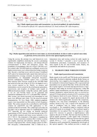
Fig. 1 Radio signal generation and transmission: (a) electrical method; (b) optical method.
E/O: electrical-to-optical; O/E: optical-to-electrical; LO: local oscillator; RF: radio frequency.
f 2 f 2
LO
f LO
λ λ
f 2 f 1 f 2 f 1
f 1 f 2
RF RF
E/O O/E E/O O/E
converter converter converter converter
(a) (b)
f 1
f 2
Sig. source
λ
f 1
λ 2 λ 1
f 2
Data
E/O O/E Laser Opt. mod. λ
converter converter λ 1 λ 0 λ 2
λ 0 (d)
(c)
λ 2
Fig. 2 Radio signal detection and down-conversion: (a) electrical method; (b) direct radio-to-optical conversion;
(c) photonic down-conversion; (d) two-tone optical signal generation.
Using the system, the antenna sites and transceivers were transparent relay and routing system for radio signals in
significantly simplified, rendering the system a promising section 4. Section 5 presents a novel system for the
solution for high-speed, low-latency, and energy-efficient simultaneous generation, transmission, and reception of
communications in FWA and emergency events. The radio signals in the 28- and 92-GHz bands. Finally, the
possibility of transmitting a line rate of up to 100 Gb/s over conclusions and outlook are presented.
the system in the 100-GHz band was confirmed, which is the
highest transmission over a direct-detection bridge system to 2. SEAMLESS FIBER–WIRELESS SYSTEM
date. Second, a dual-hop access network using a broadband
RoF system for transparent radio signal relay and routing is 2.1 Radio signal generation and transmission
demonstrated for coverage extension. As a proof-of-concept
demonstration, we transmitted orthogonal frequency- Radio signals in the mmW and THz bands can be generated
division multiplexing (OFDM) signals over a cascaded using either electrical or photonic methods. In the former, as
fiber–wireless–fiber–wireless system in the 100-GHz band shown in Fig. 1(a), a signal in a low-frequency band, such as
and achieved a line rate of up to 50 Gb/s, the highest over a the baseband or intermediate frequency (IF), is generated and
relay system reported so far. Finally, we propose and transmitted over an optical fiber link. At the end of the link,
demonstrate a novel system for the simultaneous generation, the original signal is recovered and upconverted to a high-
transmission, and reception of multiple radio signals in frequency band using an electrical upconverter. Using this
different frequency bands. Using this system, radio signals method, signal transmission over optical fiber links matures
in the 28- and 92-GHz bands can be generated and because inexpensive optical devices such as electrical-to-
transmitted simultaneously over a cascaded fiber–wireless– optical (E/O) and optical-to-electrical (O/E) converters in the
fiber system, and down-converted and transmitted to end low-frequency band can be used. However, local oscillator
users over different radio links. For the proof-of-concept (LO) sources are required for signal upconversion at the
demonstration, 5G New Radio (NR) standard-compliant antenna site, which significantly increases the complexity,
signals were transmitted over the system in both frequency footprint, cost, and power consumption. In the photonic
bands. The system can provide a cost-effective and flexible method, shown in Fig. 1(b), a signal in the baseband or IF
solution for multi-RAN and IAB applications in 5G- band is modulated onto an optical carrier signal at
Advanced and 6G networks. The technologies presented in wavelength λ1. The modulated signal is combined with an
this paper can be important topics for standardization in the optical LO signal at wavelength λ2. The combined signal is
ITU, especially for the studies on feasible technical transmitted over an optical fiber link and input to a high-
requirements of IMT towards 2030 and beyond in the ITU- speed O/E converter to generate a high-frequency radio
R and mobile transport and home access networks in the signal at the end of the link. The beat note between the two
ITU-T SG-15. The remainder of this paper is organized as optical signals generates a radio signal with a frequency
follows. Section 2 presents seamless fiber–wireless systems identical to the frequency difference between the two optical
that employ electrical and photonic methods. Section 3 signals, that is, f = |c/λ1 - c/λ2|. Radio signals at different
presents a high-speed fiber–wireless bridge system for FWA frequencies can be generated by changing the wavelength of
and emergency communications. This is followed by a the optical signal(s). This method provides a simple yet
– 34 –