
Page 81 - Kaleidoscope Academic Conference Proceedings 2024
P. 81
Innovation and Digital Transformation for a Sustainable World
CS RRH RN
100 GHz
Data Power
Power
λ 20-km fiber 100 GHz
Optical modulator 100 GHz f 4 m
Two-tone
opt. gen. 1 High-speed
Optical coupler Photodetector-1 optical modulator
A
Rx 86.5 GHz
AP
100 GHz
LD
100 GHz Power
Power
Rx. signal 2 m 100 GHz f λ
Photodetector-2 OBPF
B
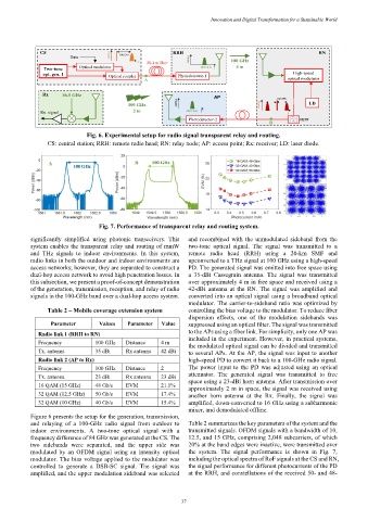
Fig. 6. Experimental setup for radio signal transparent relay and routing.
CS: central station; RRH: remote radio head; RN: relay node; AP: access point; Rx: receiver; LD: laser diode.
Fig. 7. Performance of transparent relay and routing system.
significantly simplified using photonic transceivers. This and recombined with the unmodulated sideband from the
system enables the transparent relay and routing of mmW two-tone optical signal. The signal was transmitted to a
and THz signals to indoor environments. In this system, remote radio head (RRH) using a 20-km SMF and
radio links in both the outdoor and indoor environments are upconverted to a THz signal at 100 GHz using a high-speed
access networks; however, they are separated to construct a PD. The generated signal was emitted into free space using
dual-hop access network to avoid high penetration losses. In a 35-dBi Cassegrain antenna. The signal was transmitted
this subsection, we present a proof-of-concept demonstration over approximately 4 m in free space and received using a
of the generation, transmission, reception, and relay of radio 42-dBi antenna at the RN. The signal was amplified and
signals in the 100-GHz band over a dual-hop access system. converted into an optical signal using a broadband optical
modulator. The carrier-to-sideband ratio was optimized by
Table 2 – Mobile coverage extension system controlling the bias voltage to the modulator. To reduce fiber
dispersion effects, one of the modulation sidebands was
Parameter Values Parameter Value suppressed using an optical filter. The signal was transmitted
to the APs using a fiber link. For simplicity, only one AP was
Radio link 1 (RRH to RN)
included in the experiment. However, in practical systems,
Frequency 100 GHz Distance 4 m
the modulated optical signal can be divided and transmitted
Tx. antenna 35 dBi Rx antenna 42 dBi
to several APs. At the AP, the signal was input to another
Radio link 2 (AP to Rx) high-speed PD to convert it back to a 100-GHz radio signal.
Frequency 100 GHz Distance 2 The power input to the PD was adjusted using an optical
attenuator. The generated signal was transmitted to free
Tx. antenna 23 dBi Rx antenna 23 dBi
space using a 23-dBi horn antenna. After transmission over
16 QAM (15 GHz) 48 Gb/s EVM 21.1%
approximately 2 m in space, the signal was received using
32 QAM (12.5 GHz) 50 Gb/s EVM 17.4% another horn antenna at the Rx. Finally, the signal was
32 QAM (10 GHz) 40 Gb/s EVM 15.4% amplified, down-converted to 16 GHz using a subharmonic
mixer, and demodulated offline.
Figure 6 presents the setup for the generation, transmission,
and relaying of a 100-GHz radio signal from outdoor to Table 2 summarizes the key parameters of the system and the
indoor environments. A two-tone optical signal with a transmitted signals. OFDM signals with a bandwidth of 10,
frequency difference of 84 GHz was generated at the CS. The 12.5, and 15 GHz, comprising 2,048 subcarriers, of which
two sidebands were separated, and the upper side was 20% at the band edges were inactive, were transmitted over
modulated by an OFDM signal using an intensity optical the system. The signal performance is shown in Fig. 7,
modulator. The bias voltage applied to the modulator was including the optical spectra of RoF signals at the CS and RN,
controlled to generate a DSB-SC signal. The signal was the signal performance for different photocurrents of the PD
amplified, and the upper modulation sideband was selected at the RRH, and constellations of the received 50- and 48-
– 37 –