
Page 80 - Kaleidoscope Academic Conference Proceedings 2024
P. 80
2024 ITU Kaleidoscope Academic Conference
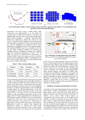
Fig. 4 Performance of fiber–wireless bridge system: (a) EVM vs. photocurrent at RAU-1; (b) constellations and
spectrum of 20-GHz bandwidth signal.
transmitted to free space using a 35-dBi antenna. After
transmission over approximately 4 m, the signal was
received using a 42-dBi antenna at RAU-2. The signal was
amplified and converted to the optical domain using a high-
speed optical modulator. A photonic downconversion
method was employed to simplify the antenna site and
receiver. Using this method, another two-tone optical signal
with a frequency separation of 84 GHz was generated at the
Rx. The two sidebands were separated, and the lower
sidebands were transmitted to RAU-2 for signal modulation.
The modulated DSB-SC signal was transmitted to the Rx,
and the upper modulated sideband was selected and
combined with the unmodulated sideband. The combined
signal with a frequency separation of 16 GHz (= 100 – 84
GHz) was input to a low-speed PD for conversion to an
Fig. 5 Schematic of radio signal relay and routing.
electrical signal. Finally, the signal was sent to a real-time
RN: relay node; T/O: terahertz-to-optical; AP: access
oscilloscope and demodulated offline. A photograph of the
point: THz: terahertz.
RAU-2 setup and the optical spectra at different points along
the system are shown in the figure. in the 0.22–0.8 mA range, attaining a line rate of 80 Gb/s.
For the 32-QAM signal, EVMs were slightly higher than the
Table 1 – Fiber–wireless bridge system
requirement. This could be caused by the low SNRs in some
subcarriers owing to the non-flat frequency response of the
Parameter Values Parameter Value
devices, which can be overcome by fully optimizing the
Frequency 100 GHz Distance 4 m system. In addition, basic digital signal processing (DSP)
Tx. antenna 35 dBi Rx antenna 42 dBi using classical methods was applied for OFDM signal
generation and demodulation. Performance and capacity can
16 QAM signal 80 Gb/s EVM 18.2%
be improved using a signal calibration algorithm or by
32 QAM signal 100 Gb/s EVM 17.9%
applying an adaptive bit and power loading to the signal. By
operating the system under optimized conditions and
The key parameters and performance of the system are listed applying a robust DSP at the receiver, a transmission
in Table 1. An OFDM signal with a bandwidth of 25 GHz at capacity of 100 Gb/s or higher can be expected for FWA and
16 GHz consisting of 2,048 subcarriers, of which 20% were emergency communications.
inactive at the band edges, was generated and transmitted,
and its performance in terms of the error vector magnitude 4. MOBILE COVERAGE EXTENSION SYSTEM
(EVM) was evaluated. The performance of the 16-QAM and
32-QAM signals for different photocurrents of the PD, A schematic of the radio signal transparent relay and routing
corresponding to different transmission powers of the THz from outdoor to indoor environments is shown in Fig. 5.
signal at RAU-1, are shown in Fig. 4 (a). Fig. 4(b) shows Radio signals can be received at relay nodes (RNs) and
examples of the constellations and spectra of the received directly converted to the optical domain for transmission to
signals. The EVM values required for the 16-QAM and 32- different access points (APs) located indoors to
QAM signals to satisfy a 20% forward error correction (FEC) communicate with end users. RNs can be installed on the
overhead are 22.09 and 15.96%, respectively [12]. The rooftops or windows of buildings to receive radio signals.
optimal performance was achieved at a photocurrent of RNs comprise a high-speed optical modulator for direct
approximately 0.4 mA. Further increasing or decreasing the THz-to-optical (T/O) conversion and radio front ends. At the
photocurrent beyond the optimal value degrades the APs, the modulated optical signals are converted back to
performance because of signal-to-noise ratio (SNR) THz signals using optical-to-THz (O/T) converters. The APs
reduction and nonlinear distortion. For the 16-QAM signal, can be flexibly placed at different locations to optimize the
satisfactory performance was obtained for the photocurrent communication capacity and coverage. RNs and APs are
– 36 –