
Page 1273 - 5G Basics - Core Network Aspects
P. 1273
Transport aspects 2
E.4 Additions to Annex B transcoding for parallel 64B/66B clients
When OPUk is large enough for the serialized 66B block stream (e.g., for 100GBASE-R client signals into
OPU4), the recovered client frames are adapted directly as per this annex.
When used in combination with the transcoding into 513B code blocks described in Annex B (e.g., for
40GBASE-R client signals into OPU3), this clause describes the additions to the Annex B transcoding process
for transport of PCS lane alignment markers.
Ethernet path monitoring is the kind of behaviour that is desirable in the case where the Ethernet
equipment and the OTN equipment are in different domains (e.g., customer and service provider) and from
the standpoint of the Ethernet equipment. It is also the default behaviour which would result from the
current mapping of 100GBASE-R where the 66B blocks would be mapped into the OPU4 container after
management of skew. It may also be perceived as a transparency requirement that BIP-8 work end-to-end.
Additional functionality as described below has to be built in to allow BIP-8 transparency for 40GBASE-R
client signals.
PCS lane alignment markers are encoded together with 66B control blocks into the uppermost rows of the
513B code block shown in Figure B.3. The flag bit "F" of the 513B structure is 1 if the 513B structure
contains at least one 66B control block or PCS lane alignment marker, and 0 if the 513B structure contains
eight all-data 66B blocks.
The transcoding into 512B/513B must encode PCS lane alignment marker into a row of the structure shown
in Figure B.3 as follows: The sync header of "10" is removed. The received M0, M1 and M2 bytes of the PCS
alignment marker encodings as shown in Table E.1 are used to forward the lane number information. The
first byte of the row will contain the structure shown in Figure B.4, with a CB-TYPE field of "0100". The POS
field will indicate the position where the PCS lane alignment marker was received among the group of eight
66B codewords being encoded into this 513B block. The flag continuation bit "FC" will indicate whether any
other 66B control blocks or PCS lane alignment markers are encoded into rows below this one in the 513B
block. Beyond this first byte, the next four bytes of the row are populated with the received M0, M1, M2 and
ingress BIP3 bytes of the PCS alignment marker encodings at the encoder. At the decoder, a PCS lane
alignment marker will be generated in the position indicated by the POS field among any 66B all-data
blocks contained in this 513B block, the sync header of "10" is generated followed by the received M0, M1
and M2 bytes, the egress BIP3 byte, the bytes M4, M5 and M6 which are the bit-wise inverted M0, M1 and M2
bytes received at the decoder, and the egress BIP7 byte which is the bit-wise inverted egress BIP3 byte.
It will then be up to the Ethernet receiver to handle bit errors within the OTN section that might have
altered the PCS alignment marker encodings (for details refer to clause 82.2.18.3 and Figure 82-11 in
[IEEE 802.3]).
The egress BIP3 and the egress BIP7 bytes are calculated as described in clause E.4.1.
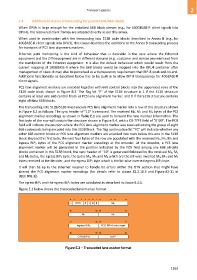
Figure E.2 below shows the transcoded lane marker format.
0 1 3 4 5 6 7 8 11 12 15
FC POS 0 1 0 0 M 0
16 23 24 31
M 1 M 2
32 39 40 47
ingress BIP 3 PCS BIP-8 error mask
48 55 56 63
OTN BIP-8 0xFF
Figure E.2 – Transcoded lane marker format
1263