
Page 1271 - 5G Basics - Core Network Aspects
P. 1271
Transport aspects 2
T
Transmission order ransmission order
1 1 Lane Marker 1 ne Marker 1
La
Lane Marker 2 ne Marker 2
2 2 La
: : : : :
La
Lane Marker p ne Marker p ne Marker p
p p La
p +1 +1
p
p x 16383 x 16383
p
66B blocks B blocks
66
p
p x 16384 x 16384
La
La
Lane Marker 1 ne Marker 1 ne Marker 1
La
La
Lane Marker 2 ne Marker 2 ne Marker 2
: : : :
La
La
Lane Marker p p p p
Lane Marker ne Marker ne Marker
p p
p x 16383 x 16383 x 16383
66
66
66B blocks B blocks B blocks
Transmission order ransmission order
0……………………...65 T
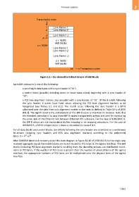
Figure E.1 – De-skewed/serialized stream of 66B blocks
Each 66B codeword is one of the following:
a set of eight data bytes with a sync header of "01";
a control block (possibly including seven or fewer data octets) beginning with a sync header of
"10";
a PCS lane alignment marker, also encoded with a sync header of "10". Of the 8 octets following
the sync header, 6 octets have fixed values allowing the PCS lane alignment markers to be
recognized (see Tables E.1 and E.2). The fourth octet following the sync header is a BIP-8
calculated over the data from one alignment marker to the next as defined in Table 82-4 of [IEEE
802.3]. The eighth octet is the complement of this BIP-8 value to maintain DC balance. Note that
the intended operation is to pass these BIP-8 values transparently as they are used for monitoring
the error ratio of the Ethernet link between Ethernet PCS sublayers. For the case of 100GBASE-R,
the BIP-8 values are not manipulated by the mapping or de-mapping procedure. For the case of
40GBASE-R, a BIP-8 compensation is done as described in clause E.4.1.
For all-data blocks and control blocks, the 64 bits following the sync header are scrambled as a continuous
bit-stream (skipping sync headers and PCS lane alignment markers) according to the polynomial
58
39
G(x) = 1 + x +x .
After 64B/66B block lock recovery as per the state diagram in Figure 82-10 of [IEEE 802.3] to the single-lane
received aggregate signal, these 66B blocks are re-distributed to PCS lanes at the egress interface. The 66B
blocks (including PCS lane alignment markers) resulting from the decoding process are distributed round-
robin to PCS lanes. If the number of PCS lanes is greater than the number of physical lanes of the egress
interface, the appropriate numbers of PCS lanes are bit-multiplexed onto the physical lanes of the egress
interface.
1261