
Page 52 - ITU Journal Future and evolving technologies Volume 2 (2021), Issue 4 – AI and machine learning solutions in 5G and future networks
P. 52
ITU Journal on Future and Evolving Technologies, Volume 2 (2021), Issue 4
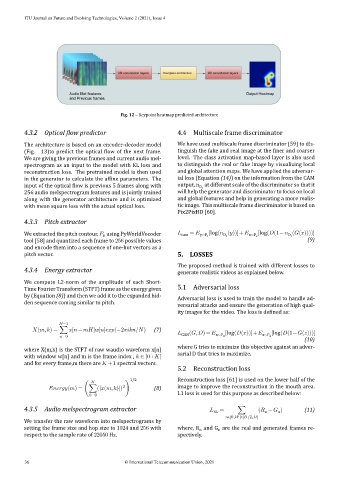
Fig. 12 – Keypoint heatmap predicted architecture
4.3.2 Optical low predictor 4.4 Multiscale frame discriminator
The architecture is based on an encoder‑decoder model We have used multiscale frame discriminator [59] to dis‑
(Fig. 13)to predict the optical low of the next frame. tinguish the fake and real image at the iner and coarser
We are giving the previous frames and current audio mel‑ level. The class activation map‑based layer is also used
spectrogram as an input to the model with KL loss and to distinguish the real or fake image by visualizing local
reconstruction loss. The pretrained model is then used and global attention maps. We have applied the adversar‑
in the generator to calculate the af ine parameters. The ial loss (Equation (14)) on the information from the CAM
input of the optical low is previous 5 frames along with output, n at different scale of the discriminator so that it
D t
256 audio melspectrogram features and is jointly trained will help the generator and discriminator to focus on local
along with the generator architecture and is optimized and global features and help in generating a more realis‑
with mean square loss with the actual optical loss. tic image. This multiscale frame discriminator is based on
Pix2PixHD [60].
4.3.3 Pitch extractor
We extracted the pitch contour, using PyWorldVocoder cam = y∼P t [log( ( ))]+ x∼P s [log( (1− ( ( ))))]
0
D t
D t
tool [58] and quantized each frame to 256 possible values (9)
and encode them into a sequence of one‑hot vectors as a
pitch vector. 5. LOSSES
The proposed method is trained with different losses to
4.3.4 Energy extractor generate realistic videos as explained below.
We compute L2‑norm of the amplitude of each Short‑
Time Fourier Transform (STFT) frame as the energy given 5.1 Adversarial loss
by (Equation (8)) and then we add it to the expanded hid‑ Adversarial loss is used to train the model to handle ad‑
den sequence coming similar to pitch. versarial attacks and ensure the generation of high qual‑
ity images for the video. The loss is de ined as:
−1
( , ) = ∑ [ − ] [ ] (−2 / ) (7) ( , ) = [log( ( ))]+ [log( (1− ( )))]
=0 GAN x∼P d z∼P z
(10)
where G tries to minimize this objective against an adver‑
where X(m,k) is the STFT of raw waudio waveform x[n]
with window w[n] and m is the frame index , ∈ [0 ∶ ] sarial D that tries to maximize.
and for every frame,m there are +1 spectral vectors.
5.2 Reconstruction loss
1/2 Reconstruction loss [61] is used on the lower half of the
2
( ) = (∑(| ( , )|) ) (8) image to improve the reconstruction in the mouth area.
=0 L1 loss is used for this purpose as described below:
4.3.5 Audio melspectrogram extractor RL = ∑ ( − ) (11)
n
n
[0, ]∗[ /2, ]
We transfer the raw waveform into melspectrograms by
setting the frame size and hop size to 1024 and 256 with where, R and G are the real and generated frames re‑
n
n
respect to the sample rate of 22050 Hz. spectively.
36 © International Telecommunication Union, 2021