
Page 104 - Kaleidoscope Academic Conference Proceedings 2020
P. 104
2020 ITU Kaleidoscope Academic Conference
pattern from semi-static to dynamic, so that the indication For a UL CI based solution, the remaining part of eMBB
pattern can be adjusted flexibly according to the service transmission is dropped by assuming phase continuity of UL
arrival to obtain a more accurate indication. This can reduce eMBB transmission cannot be guaranteed. For a UL power
the false indication and protect the eMBB service. Then, a control based solution, P dB power boosting of URLLC
resource occupancy based power control (ROPC) is transmission is assumed in case of overlapping with grant-
proposed to enhance the current BPC method. Based on based eMBB transmission respectively. In our simulation,
ROPC, it becomes possible for gNB to dynamically indicate each PDCCH monitoring occasion occupies one symbol with
different power control parameters to user equipment (UE) 32 CCEs. When considering reserving some candidates for
on different sets of time-frequency resource, which will eMBB scheduling, the PDCCH search space set
further ensure URLLC transmission performance and protect configuration for UL cancellation signaling is assumed as the
the normal eMBB transmission. Furthermore, a dynamic aggregation level (AL)={1,2,4,8,16} with corresponding
selection of DPCI and ROPC is proposed. Because the scene candidate numbers {4,4,2,1,1} respectively. The AL of the
is complex in real deployment, each multiplexing UL cancellation signaling is selected according to a PDCCH
mechanism has its own advantages and disadvantages, and a channel condition with a target BLER requirement. For a UL
combination of them will get more robust and better cancellation based solution, a group common PDCCH is
performance. adopted. In addition, the additional signaling caused by
method improvement is carried by the PDCCH.
The paper is organized as follows. Section 2 introduces the
service multiplexing system model. In section 3, the
proposed design of DPCI, ROPC and the dynamic selection slot n slot n+1 slot n+2
mechanism is described in detail. Extensive system level
simulation results are introduced in section 4, and the 0 1 2 3 4 5 6 7 8 9 10 11 12 13
conclusion of this paper is given in section 5. eMBB TTI
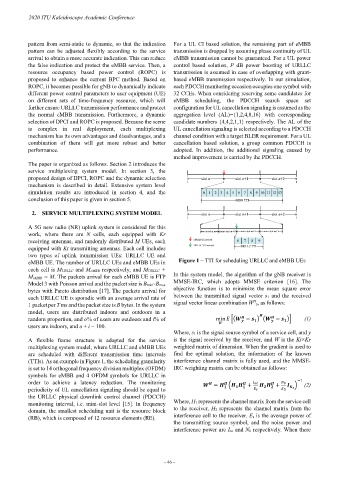
2. SERVICE MULTIPLEXING SYSTEM MODEL slot n slot n+1 slot n+2
A 5G new radio (NR) uplink system is considered for this
work, where there are N cells, each equipped with Kr mini-slot m mini-slot m+1 mini-slot m+2 mini-slot m+3
receiving antennas, and randomly distributed M UEs, each eMBB UE arrival 6 7 8 9
equipped with Kt transmitting antennas. Each cell includes URLLC UE arrival URLLC TTI
two types of uplink transmission UEs: URLLC UE and
eMBB UE. The number of URLLC UEs and eMBB UEs in Figure 1 – TTI for scheduling URLLC and eMBB UEs
each cell is M URLLC and MeMBB respectively, and MURLLC +
MeMBB = M. The packets arrival for each eMBB UE is FTP In this system model, the algorithm of the gNB receiver is
Model 3 with Poisson arrival and the packet size is Bmin~Bmax MMSE-IRC, which adopts MMSE criterion [16]. The
bytes with Pareto distribution [17]. The packets arrival for objective function is to minimize the mean square error
each URLLC UE is sporadic with an average arrival rate of between the transmitted signal vector s1 and the received
H
1 packet per T ms and the packet size is B bytes. In the system signal vector linear combination W y, as follows:
model, users are distributed indoors and outdoors in a
random proportion, and o% of users are outdoors and i% of min �� − � � − �� (1)
users are indoors, and o + i = 100.
Where, s 1 is the signal source symbol of a service cell, and y
A flexible frame structure is adopted for the service is the signal received by the receiver, and W is the Kt×Kr
multiplexing system model, where URLLC and eMBB UEs weighted matrix of dimension. When the gradient is used to
are scheduled with different transmission time intervals find the optimal solution, the information of the known
(TTIs). As an example in Figure 1, the scheduling granularity interference channel matrix is fully used, and the MMSE-
is set to 14 orthogonal frequency division multiplex (OFDM) IRC weighting matrix can be obtained as follows:
symbols for eMBB and 4 OFDM symbols for URLLC in
order to achieve a latency reduction. The monitoring = � + + 0 � (2)
−1
periodicity of UL cancellation signaling should be equal to
the URLLC physical downlink control channel (PDCCH)
monitoring interval, i.e. mini-slot level [15]. In frequency Where, H1 represents the channel matrix from the service cell
domain, the smallest scheduling unit is the resource block to the receiver, H2 represents the channel matrix from the
(RB), which is composed of 12 resource elements (RE). interference cell to the receiver. Es is the average power of
the transmitting source symbol, and the noise power and
interference power are I oc and N 0 respectively. When there
– 46 –