
Page 746 - 5G Basics - Core Network Aspects
P. 746
2 Transport aspects
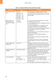
Table 9-8 – Upstream RMC command (sent by FTU-R only)
Field name Format Description
Retransmission ACK bit- Six bytes ACK bitmap [b47 ...b0], the bit b0 relates to the last
map byte 0: [b7 ... b0] transmitted DTU(s) in the ACK window (see clause 9.7).
byte 1: [b15... b8] Any given bit of the ACK bitmap shall be set to 1 for ACK
byte 2: [b23 ... b16] and 0 for NACK.
byte 3: [b31 ... b24]
byte 4: [b39 ... b32]
byte 5: [b47 ... b40]
Retransmission ACK One byte: aa = ACK group size (Gack) represented as an unsigned
group size, RMC ACK, [dddd aabc] integer with valid values 1, 2, 3.
TIGA ACK and indicator b = acknowledgement of the RMC message; shall be set to
bits 1 for ACK and 0 for NACK.
c = positive acknowledgement of reception of an OLR
request type 3 (TIGA) eoc command (TIGA-ACK).
c=1 indicates that a transmitter-initiated gain adjustment
(TIGA) command was received and positively
acknowledged.
c=0 indicates that no TIGA command was received and
positively acknowledged.
The generation and use of this bit is specified in
clause 13.2.2.1.
dddd = indicator bits according to the following order:
[lpr los lom lor].
An indicator bit shall be set to 0 if the corresponding
primitive/defect occurs and set to 1 otherwise (active
low).
Upstream logical frame Three bytes Configuration parameters to be used for the current
configuration logical frame or for the following frame, depending on the
value of MB upstream (see clause 10.7 and Table 12-41)
The format of logical frame configuration parameters is
specified in Table 9-9.
Expected transmission One byte: [000 aaaaa] aaaaa = expected transmission time expressed in symbols
time (ETT) for the current logical frame, specified as the symbol
position index of the last data symbol expected to be
transmitted in the logical frame. The actual transmission
time shall be less than or equal to the value
communicated (Note 1).
DTU sync value (NB) Two bytes: The value of NB, for the current logical frame (see
byte 0 [s7 ... s0] definition of NB in clause 9.5) expressed in bytes:
byte 1 [0000 s11... s8] The value is coded as a 12 bit unsigned integer [s11 ... s0]
with s0 the LSB.
The valid range for the DTU sync value is 00016 to FFF16.
736