
Page 724 - 5G Basics - Core Network Aspects
P. 724
2 Transport aspects
same order that they were received from the γ reference point and TPS-TC_MGMT interface, respectively,
at the transmit end.
8.2.3 Error check sequence (ECS)
The ECS field is for DTU verification. The ECS shall contain a 32-bit cyclic redundancy check (CRC) that shall
be computed over the DTU header and DTU payload bytes in the order that they are transmitted, starting
with the LSB of the first byte of the DTU header (SID field in clause 8.2.1.1) and ending with the MSB of the
last byte of the DTU payload.
The ECS shall be computed using the following generator polynomial of degree 32:
23
22
20
25
28
32
26
27
9
10
6
8
11
18
19
13
14
G(D) = D +D +D +D +D +D +D +D +D +D +D +D +D +D +D +D +D +1
The value of ECS shall be the remainder after all bits of the DTU subject to CRC treated as an input
32
polynomial, are multiplied by D and then divided by G(D). For a t-bit input polynomial, the CRC shall be
computed using the following equation:
32
crc(D)= M(D) D modulo G(D),
where:
t–2
M(D) = m0D + m1D + … + mt–2D + mt–1 is the t-bit polynomial where m0 is the LSB of the
t–1
first byte of the header and mt-1 is the MSB of the last byte of the DTU payload,
30
31
crc(D) = crc0D + crc1D + … + crc30D + crc31 is the CRC polynomial where crc0 is the LSB of
the first byte of the ECS field and crc31 is the MSB of the last byte of the ECS field,
and
D is the delay operator.
The arithmetic in this clause shall be performed in the Galois Field GF(2).
8.3 Packet-based TPS-TC (PTM-TC)
8.3.1 PTM-TC DTU format
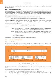
The generic format of a DTU is presented in Figure 8-4. This clause defines the format of the DTU payload
that shall be used for a PTM-TC DTU. The format of the DTU payload is shown in Figure 8-6.
Figure 8-6 – PTM-TC DTU payload format
The DTU payload consists of a number of DTU frames, each DTU frame containing a DTU frame header and
DTU frame payload.
The DTU frame header shall be either one byte or two bytes long and indicates:
– the type of the DTU frame coded on four bits [t3 t2 t1 t0], where t0 represents the LSB;
– the length of the DTU frame payload in bytes coded as either a 4-bit [l3 ... l0] or a 12-bit [l11...l0]
unsigned integer, where l0 represents the LSB.
714