
Page 722 - 5G Basics - Core Network Aspects
P. 722
2 Transport aspects
Table 8-8 – Summary of the TPS-TC_MGMT primitives
Primitive Direction Description
KFEC FME → TPS-TC The number of information bytes of a FEC codeword, see clause 9.3.
Q FME → TPS-TC The number of FEC codewords in a single DTU, see clause 8.5.
eoc message, TX FME → TPS-TC TX eoc message primitives, see clause 11.2.2.
eoc message, RX TPS-TC → FME RX eoc message primitives, see clause 11.2.2.
FCus TPS-TC → FME Upstream flow control to be communicated over the RMC (see clause
9.6.4 and Table 9-5).
TPS_TESTMODE FME → TPS-TC A management primitive initiating the TPS-TC test mode (see clause
9.8.3.1.2).
Symbol count FME → TPS-TC Count of DMT symbols (see clause 8.2.1.2 and clause 10.6).
(CNTSYMB)
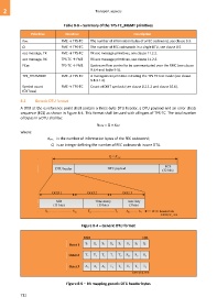
8.2 Generic DTU format
A DTU at the α reference point shall contain a three-byte DTU header, a DTU payload and an error check
sequence (ECS) as shown in Figure 8-4. This format shall be used with all types of TPS-TC. The total number
of bytes in a DTU shall be:
NDTU = Q × KFEC
where:
KFEC is the number of information bytes of the FEC codeword;
Q is an integer defining the number of FEC codewords in one DTU.
Figure 8-4 – Generic DTU format
Figure 8-5 – Bit mapping generic DTU header bytes
712