
Page 597 - 5G Basics - Core Network Aspects
P. 597
Transport aspects 2
7 Fundamental technologies
7.1 Electrical-to-optical conversion
7.1.1 Direct modulation
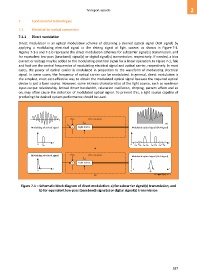
Direct modulation is an optical modulation scheme of obtaining a desired optical signal (RoF signal) by
applying a modulating electrical signal to the driving signal of light source, as shown in Figure 7-1.
Figures 7-1-a and 7-1-b represent the direct modulation schemes for subcarrier signal(s) transmission, and
for equivalent low-pass (baseband) signal(s) or digital signal(s) transmission, respectively. If needed, a bias
current or voltage may be added to the modulating electrical signal for a linear operation. In Figure 7-1, fele
and fopt are the central frequencies of modulating electrical signal and optical carrier, respectively. In most
cases, the power of optical carrier is modulated in proportion to the waveform of modulating electrical
signal. In some cases, the frequency of optical carrier can be modulated. In general, direct modulation is
the simplest, most cost-effective way to obtain the modulated optical signal because the required optical
device is just a laser source. However, some intrinsic characteristics of the light source, such as nonlinear
input-output relationship, limited driver bandwidth, relaxation oscillation, chirping, pattern effect and so
on, may often cause the distortion of modulated optical signal. To prevent this, a light source capable of
producing the desired system performance should be used.
t Bias E/O converter
t
f opt
f ele
Modulating electrical signal + Light source Modulated optical signal (RoF signal)
... ...
f f
0 f ele 0 f opt –2 f ele f opt – f ele f opt + f ele f opt +2 f ele
a)
Modulating electrical signal Bias E/O converter Modulated optical signal (RoF signal)
f opt
+ Light source
f f
0 0 f opt
b) G Suppl.55(15)_F7-1
Figure 7-1 – Schematic block diagram of direct modulation: a) for subcarrier signal(s) transmission; and
b) for equivalent low-pass (baseband) signal(s) or digital signal(s) transmission
587