
Page 593 - 5G Basics - Core Network Aspects
P. 593
Transport aspects 2
Downlink Downlink digitized
digitized Optical transceiver Optical transceiver RF-band subcarrier
Downlink Digital RF-band
payload data RF-band subcarrier E/O Digital RoF O/E D/A RF-band Downlink
(digital baseband) modulator converter converter converter filter RF signal
Uplink Fibre-optic
digitized MUX/DEMUX link MUX/DEMUX
RF-band
Uplink Digital
payload data RF-band subcarrier O/E E/O A/D RF-band Uplink
(digital baseband) demodulator converter Digital optical converter converter filter RF signal
interfaces
Uplink digitized
a) RF-band subcarrier
Downlink Optical transceiver Optical transceiver Downlink digitized
digitized IF-band subcarrier
Downlink Digital IF-band
payload data IF-band subcarrier E/O Digital RoF O/E D/A IF-to-RF Downlink
(digital baseband) modulator converter converter converter converter RF signal
Uplink
digitized MUX/DEMUX Fibre-optic MUX/DEMUX
link
Uplink Digital IF-band
payload data IF-band subcarrier O/E E/O A/D RF-to-IF Uplink
(digital baseband) demodulator converter Digital optical converter converter converter RF signal
interfaces
Uplink digitized
IF-band subcarrier Reference frequency
b) for up/down convertion
Downlink Downlink digitized
digitized Optical transceiver Optical transceiver I/Q baseband signals
I/Q baseband
Downlink signals Downlink
payload data Digital I/Q E/O Digital RoF O/E D/A I/Q-to-RF
(digital baseband) modulator converter converter converter converter RF signal
Uplink
digitized MUX/DEMUX Fibre-optic MUX/DEMUX
I/Q baseband link
Uplink signals
payload data Digital I/Q O/E E/O A/D RF-to-I/Q Uplink
(digital baseband) demodulator converter Digital optical converter converter converter RF signal
interfaces
Uplink digitized
I/Q baseband signals Reference frequency
c) for up/down convertion
G Suppl.55(15)_F6-4
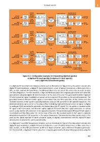
Figure 6-4 – Configuration examples for transmitting digitized signal(s):
a) digitized RF-band signal(s); b) digitized IF-band signal(s);
and c) digitized I/Q baseband signal(s)
In a digitized RF-band RoF transmission scheme such as that shown in Figure 6-4-a, the system consists of a
digital RF-band modulator, a digital RF-band demodulator, a pair of optical transceivers, a fibre-optic link, a
DAC, an ADC, and two RF-band filters. The RF-band filters may be used if the need arises in order to obey
the Radio Regulation. For the downlink, a digitized RF-band subcarrier is digitally generated with downlink
payload data using the digital RF-band modulator at the local office end. The generated downlink digitized
RF-band subcarrier signal modulates an optical carrier using an E/O converter in the optical transceiver. The
generated downlink RF-band D-RoF signal is transmitted over the fibre-optic link. At the remote end, the
received downlink D-RoF signal is optically detected using an O/E converter in the optical transceiver. The
detected electrical signal, which is the same as the modulating digitized RF-band subcarrier signal, is digital
to analogue (D/A) converted to generate the desired downlink RF signal. For the uplink, a received uplink
RF signal is A/D converted, and then the uplink digitized RF-band subcarrier signal modulates an optical
carrier using another E/O converter in the optical transceiver. The generated uplink RF-band D-RoF signal is
transmitted over the fibre-optic link. At the local office end, the received uplink D-RoF signal is optically
detected using another O/E converter in the optical transceiver. The detected electrical signal, which is the
same as the uplink digitized RF-band subcarrier signal, is digitally demodulated with the digital RF-band
demodulator to recover the uplink payload data.
In a digitized IF-band RoF transmission scheme, such as that shown in Figure 6-4-b, the system consists of a
digital IF-band modulator, a digital IF-band demodulator, a pair of optical transceivers, a fibre-optic link, a
DAC, an ADC, an IF-to-RF up-converter, an RF-to-IF down-converter, and a reference frequency generator.
For the downlink, a digitized IF-band subcarrier is digitally generated with downlink payload data using the
583