
Page 602 - 5G Basics - Core Network Aspects
P. 602
2 Transport aspects
C-RAN central office
Digital channel Hig -speedh
... aggregation DAC PA Laser Fibre
BBU
digital Optical
baseband circulator Mobile
processing front-haul
... Digital channel High-speed PA PD link
de-aggregation
ADC
RRU site DAC FUC Antenna
High-speed Digital channel
PD PA .. ..
ADC de-aggregation . .
DAC FUC
Optical Duplexer Antenna
circulator array ...
ADC FDC
Hig -speedh Digital channel
Laser PA .. ..
DAC aggregation . .
ADC FDC
G Suppl.55(15)_F7-6
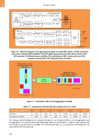
Figure 7-6 – Schematic diagram of an aggregated analogue RoF based MFH system. C-RAN: centralized
radio access network; BBU: baseband unit; DSP: digital signal processing; DAC: D/A converter; ADC:
A/D converter; PA: RF-band power amplifier; PD: photodetector; RRU: remote radio unit; FUC:
frequency-up-converter; FDC: frequency-down-converter
Different wireless channels
for different RRHs, sectors,
and services.
Aggregated channels
(for optical transm ssion withi
shared optical hardware)
Channel
aggregator
Frequency
G Suppl.55(15)_F7-7
Frequency
Figure 7-7 – Illustration of the channel aggregation principle
Table 7-1 – Typical channel bandwidth and sampling rates for E-UTRA
Channel bandwidth (MHz) 1.4 3 5 10 15 20
FFT size 128 256 512 1 024 1 536 2 048
Sampling rate (MHz) 1.92 3.84 7.68 15.36 23.04 30.72
The analogue RoF technology can be extended to allow the use of modest DSP for channel aggregation and
de-aggregation. This would achieve high bandwidth efficiency and flexibility. In addition, the analogue RoF
technology can be backward-compatible with CPRI-based D-RoF, e.g., by separately transmitting the I/Q
data and the CPRI control words.
592