
Page 592 - 5G Basics - Core Network Aspects
P. 592
2 Transport aspects
6.2 Digital RoF system
6.2.1 Digital radio signal(s) transmission
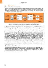
Figure 6-3 illustrates general and fundamental architectures for transmitting digital radio signals. RF-band
pulse(s), such as impulse radio signal(s), is a typical example of the digital radio signal(s). In Figure 6.3, it is
assumed that equipment on the left side of the fibre-optic link is located in the local office and equipment
on the right side is located at the remote antenna.
Downlink Optical transceiver Optical transceiver Downlink
digital RF- digital RF-
Downlink RF-band band pulse band pulse
payload data pulse E/O Digital RoF E/O RF-band Downlink
(digital baseband) generator converter converter filter RF signal
Uplink Fibre-optic Uplink
digital RF- MUX/DEMUX link MUX/DEMUX digital RF-
Uplink RF-band band pulse band pulse
payload data pulse O/E O/E RF-band Uplink
(digital baseband) detector converter converter filter RF signal
Digital optical
interfaces
G Suppl.55(15)_F6-3
Figure 6-3 – Configuration examples for transmitting digital signal(s): RF-band pulse
In a RF-band pulse transmission scheme, such as that shown in Figure 6-3, the system consists of an
RF-band pulse generator, a RF-band pulse detector, a pair of optical transceivers, a fibre-optic link, and two
RF-band filters. The RF-band filters may be used if the need arises in order to obey the Radio Regulation.
For the downlink, an RF-band pulse is generated with downlink payload data using the RF-band pulse
generator at the local office end. The generated downlink RF-band pulse modulates an optical carrier using
an E/O converter in the optical transceiver. The generated downlink digital RoF signal is transmitted over
the fibre-optic link. It is noted that, although an optical interface of the fibre-optic link is treated as digital,
the nature of the interface may be close to analogue. This is because the intensity of optical signal may
have analogue value, such as monocycle pulse, doublet pulse and so on. At the remote end, the received
downlink RoF signal is optically detected using an O/E converter in the optical transceiver. The detected
electrical signal, which is the same as the modulating RF-band pulse, becomes the desired downlink RF
signal. For the uplink, a received uplink RF signal, which corresponds to an uplink RF-band pulse, modulates
an optical carrier using another E/O converter in the optical transceiver. The generated uplink digital RoF
signal is transmitted over the fibre-optic link. At the local office end, the received uplink RoF signal is
optically detected using another O/E converter in the optical transceiver. The detected electrical signal,
which is the same as the uplink RF-band pulse, is demodulated with the RF-band pulse detector to recover
the uplink payload data.
6.2.2 Digitized radio signal(s) transmission
Figure 6-4 illustrates general and fundamental architectures for transmitting digitized radio signals, such as
digitized RF-band subcarrier, digitized IF-band subcarrier, and digitized I/Q baseband signals. In Figure 6-4,
it is assumed that equipment on the left side of the fibre-optic link is located in the local office and
equipment on the right side is located at the remote antenna.
582