
Page 599 - 5G Basics - Core Network Aspects
P. 599
Transport aspects 2
O/E converter t
t
f ele
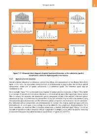
Received optical signal (RoF signal) Photodetector Electrical filter Recovered electrical signal
Bias
... ... f f
0 f opt –2 f ele f –f ele f opt + f ele f opt +2 f ele 0 f ele
opt
... ... f
0 f opt –2 f ele f –f ele f opt + f ele f opt +2 f ele
opt
For envelope detection using all components
a)
O/E converter Modulating electrical signal
Modulated optical signal (RoF signal)
f ele
Photodetector Electrical filter
f f
0 f opt Bias 0
G Suppl.55(15)_F7-3
f
0 f opt
b)
Figure 7-3 – Schematic block diagram of optical incoherent detection: a) for subcarrier signal(s)
transmission; and b) for digital signal(s) transmission
7.2.2 Optical coherent detection
Optical coherent detection is a detection scheme that allows the measurement of the electric field of the
signal. In this case, the square-law mixing function of photodetector is used to beat two or more optical
components, where one of optical components is a reference signal. The reference signal may be
modulated or not.
As an example, Figure 7-4 is a schematic block diagram of optical coherent detection. In Figure 7-4-a, which
is an example of optical self-heterodyne detection, a received optical signal (RoF signal) put into an optical
filter to extract, for example, the modulated optical component at fopt + fele and the reference optical
component at fopt. It is noted that the optical filter in the O/E converter may be able to be omitted if only
the modulated optical component and the reference optical component are received at the O/E converter.
The extracted optical components are photodetected to recover the original electrical signal with the
photodetector. In most cases, a bias voltage should be added to the output port of photodetector for a
linear operation. An electrical filter is used to extract only a desired electrical signal. Figure 7-4-b is an
example of optical homodyne detection with an independent local light source, which is used for detecting
an equivalent low-pass (equivalent bandpass) signal shown in Figures 6-2 and 6-5-c.
589