
Page 600 - 5G Basics - Core Network Aspects
P. 600
2 Transport aspects
O/E converter t
t ex. f and f + f ele
opt
opt
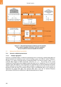
Received optical signal (RoF signal) Optical filter Photodetector Electrical filter f ele Recovered electrical signal
Bias
... ... f Pass bandwidth f
0 f opt –2 f ele f opt – f ele f opt + f ele f opt +2 f ele 0 f ele
... ...
0 f opt –2 f ele f opt – f ele f opt + f ele f opt +2 f ele f
For beating two selected components
a)
Received optical signal O/E converter
(equivalent low-pass signal)
Photodetector Electrical filter I-channel signal
90-degree
f hybrid
0 f opt optical Bias
coupler
Local light Photodetector Electrical filter Q-channel signal
Bias
Local light source
f
0
G Suppl.55(15)_F7-4
f opt
b)
Figure 7-4 – Schematic block diagram of optical coherent detection:
a) for subcarrier signal(s) transmission; and b) for equivalent
low-pass (equivalent baseband) signal(s) transmission
7.3 High-spectral-efficient transmission
7.3.1 Subcarrier multiplexing transmission
7.3.1.1 Analogue aggregation
Subcarrier multiplexing (SCM) is an electrical multiplexing scheme of obtaining a desired driving signal for
optical modulation by combining several electrical bandpass signals with different central frequencies.
Therefore, it is a kind of frequency division multiplexing (FDM) in the electrical domain. Figure 7-5 is a
schematic block diagram of SCM transmission, where fen (n = 1, 2, …, N) and fopt are the central
frequencies of modulating electrical bandpass signals and optical carrier, respectively. At first, the electrical
bandpass signals with different central frequencies are combined with an electrical frequency multiplexer
(MUX) to generate an SCM signal. The SCM signal modulates an optical carrier with an E/O converter to
generate an SCM RoF signal. The received SCM RoF signal is photodetected with an O/E converter to
regenerate the original SCM signal. The recovered SCM signal is put into an electrical frequency
demultiplexer (DEMUX) to be divided into N original modulating electrical signals.
590