
Page 589 - 5G Basics - Core Network Aspects
P. 589
Transport aspects 2
6 System architectures
Based on the RoF concept, various system architectures are considered. When a system consisting of one
base station (BS) and many remote antenna sites, which is a typical model of RoF systems, is considered, it
falls into one of two categories that differ in the types of signal transmitted over the fibre-optic link. One is
a system for transmitting subcarrier signal(s), and the other is a system for transmitting equivalent low-pass
signal(s). In addition, system architectures for relay transmission are important for radio shadow
countermeasure applications. Their system architectures and their features are explained here in detail.
Here, it is noted that the system architectures shown in this clause are typical examples and that other
system architectures are conceivable.
6.1 Analogue RoF system
6.1.1 Subcarrier signal(s) transmission
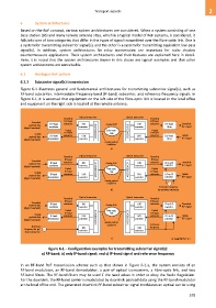
Figure 6-1 illustrates general and fundamental architectures for transmitting subcarrier signal(s), such as
RF-band subcarrier, intermediate-frequency-band (IF-band) subcarrier, and reference frequency signals. In
Figure 6-1, it is assumed that equipment on the left side of the fibre-optic link is located in the local office
and equipment on the right side is located at the remote antenna.
Optical transceiver Optical transceiver
Downlink Downlink
RF-band RF-band
Downlink
payload data RF-band subcarrier E/O Analog RoF O/E subcarrier RF-band Downlink
(digital baseband) modulator converter converter filter RF signal
Uplink MUX/DEMUX Fibre-optic MUX/DEMUX Uplink
RF-band link RF-band
Uplink
payload data RF-band subcarrier O/E E/O subcarrier RF-band Uplink
(digital baseband) demodulator converter converter filter RF signal
Analog optical
interfaces
a)
Downlink Optical transceiver Optical transceiver Downlink
IF-band IF-band
Downlink
IF-to-RF
payload data IF-band subcarrier E/O Analog RoF O/E subcarrier converter Downlink
RF signal
(digital baseband) modulator converter converter
Uplink Fibre-optic Uplink
IF-band MUX/DEMUX link MUX/DEMUX IF-band
Uplink
RF-to-IF
payload data IF-band subcarrier O/E E/O subcarrier converter Uplink
RF signal
(digital baseband) demodulator converter converter
Analog optical
interfaces
Reference frequency
b) for up/down convertion
Optical transceiver Optical transceiver
Downlink Downlink
IF-band RF-band
Downlink subcarrier subcarrier Downlink
payload data IF-band E/O Analog RoF O/E IF-to-RF
(digital baseband) modulator converter converter converter RF signal
Uplink Fibre-optic Uplink
RF-band
IF-band
Uplink subcarrier link subcarrier Uplink
payload data IF-band O/E MUX/DEMUX MUX/DEMUX E/O RF-to-IF
(digital baseband) demodulator converter Analog optical converter converter RF signal
Reference interfaces Reference
frequency
frequency for up/ E/O O/E
down convertion converter converter
c) G Suppl.55(15)_F6-1
Figure 6-1 – Configuration examples for transmitting subcarrier signal(s):
a) RF-band; b) only IF-band signal; and c) IF-band signal and reference frequency
In an RF-band RoF transmission scheme such as that shown in Figure 6-1-a, the system consists of an
RF-band modulator, an RF-band demodulator, a pair of optical transceivers, a fibre-optic link, and two
RF-band filters. The RF-band filters may be used if the need arises in order to obey the Radio Regulation.
For the downlink, the RF-band carrier is modulated by downlink payload data using the RF-band modulator
at the local office end. The generated downlink RF-band subcarrier signal modulates an optical carrier using
579