
Page 591 - 5G Basics - Core Network Aspects
P. 591
Transport aspects 2
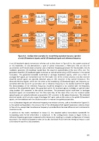
Downlink Optical transceiver Optical transceiver Downlink
I/Q baseband I/Q baseband
Downlink signals signals
payload data I/Q E/O Analog RoF O/E I/Q-to-RF Downlink
(digital baseband) modulator converter converter converter RF signal
Uplink MUX/DEMUX Fibre-optic MUX/DEMUX Uplink
I/Q baseband link I/Q baseband
Uplink signals signals
payload data I/Q O/E E/O RF-to-I/Q Uplink
(digital baseband) demodulator converter converter converter RF signal
Analog optical
interfaces
Reference frequency
a) for up/down conversion
Downlink Optical transceiver Optical transceiver Downlink
I/Q baseband I/Q baseband
Downlink signals signals Downlink
payload data I/Q E/O Analog RoF O/E I/Q-to-RF
(digital baseband) modulator converter converter converter RF signal
Uplink Fibre-optic Uplink
I/Q baseband link I/Q baseband
Uplink
payload data IF-band signals O/E MUX/DEMUX MUX/DEMUX E/O signals RF-to-I/Q Uplink
RF signal
(digital baseband) demodulator converter Analog optical converter converter
Reference frequency E/O interfaces O/E Reference
frequency
(analog electrical
signal) converter converter
b) G Suppl.55(15)_F6-2
Figure 6-2 – Configuration examples for transmitting equivalent low-pass signal(s):
a) only I/Q baseband signals; and b) I/Q baseband signals and reference frequency
In an I/Q baseband signals transmission scheme such as that shown in Figure 6-2-a, the system consists of
an I/Q modulator, an I/Q demodulator, a pair of optical transceivers, a fibre-optic link, an I/Q-to-RF
up-converter, an RF-to-I/Q down-converter, and a reference frequency generator. For the downlink, the I/Q
modulator generates I/Q baseband signals from the downlink payload data at the local office end. The
generated downlink I/Q baseband signals modulate an optical carrier using an E/O converter in the optical
transceiver. The generated downlink multi-level or analogue baseband signals, which are a form of
analogue RoF signal, are transmitted over the fibre-optic link. At the remote antenna end, the received
downlink optical signals are optically detected using an O/E converter in the optical transceiver. The
detected electrical signals, which are the same as the modulating I/Q baseband signal, are frequency up-
converted with the I/Q-to-RF up-converter and a reference frequency to the desired downlink RF signal.
The characteristics of the reference frequency should be designed to be satisfied with the frequency
stability of the downlink RF signal. The generated uplink I/Q baseband signals modulate an optical carrier
using another E/O converter in the optical transceiver. The generated uplink multi-level or analogue
baseband signals are transmitted over the fibre-optic link. At the local office end, the received uplink
optical signals are optically detected using another O/E converter in the optical transceiver. The detected
electrical signals, which are also a type of analogue RoF signal, and are the same as the uplink I/Q baseband
signals, are demodulated with the I/Q demodulator to recover the uplink payload data.
In an I/Q baseband signals and reference frequency transmission scheme, such as that shown in Figure 6-2-
b, the system configuration is the same as that of the I/Q baseband RoF signal transmission scheme shown
in Figure 6-2-a, except that the reference frequency is provided from the local office end and is delivered to
the antenna site.
In addition to the merits mentioned in clause 6.1, the required optical transmission bandwidth for
transporting radio format information is minimized. In the configurations shown in Figure 6-2-b, no
reference frequency generator is required at the remote end, resulting in a simpler configuration of remote
equipment. The reference frequency value can be also decreased if sub-harmonic mixing technique is used
in the IQ-to-RF and RF-to-I/Q converters.
581