Page 324 - Kaleidoscope Academic Conference Proceedings 2024
P. 324

2024 ITU Kaleidoscope Academic Conference


                                    control link  IRS         denoted by h     ∈  C     ×1 , Θ  ∈  C    ×    and G  ∈
                                            controller           ×  
                       IRS                                    C    . Wherein, the reflection-coefficient matrix is Θ =

                                                                            1            
                                                              diag    1     , · · · ,           , in which       ∈ [0, 2  ], ∀   ∈
                                    G
                          k h                                 N represent the phase shift, and the amplitude reflection
                    User 1                                    coefficient is fixed as       = 1, ∀   ∈ N. Thus, the effective
                                                  MEC server
                                                              channel between user    and AP can be represented as
                    User k
                               h  , a k
                    User K                                                   h    (  ) = GΘh    + h   ,   ,  (1)
                                             AP
                                                              in which    represents nonzero elements of matrix Θ.
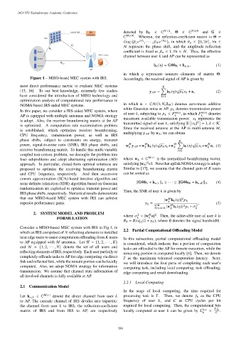
                Figure 1 – MISO-based MEC system with IRS.    Accordingly, the received signal of AP is given by
           most direct performance metric to evaluate MEC systems
                                                                                        √
                                                                                    ∑︁
           [15, 16].  To our best knowledge, extremely few studies         y      =  h    (  )             + n,  (2)
           have considered the introduction of MISO technology and                 =1
           optimization analysis of computational rate performance in
           NOMA-based IRS-aided MEC systems.                  in which n ∼ CN (0,    0 I    ) denotes zero-mean additive
                                                              white Gaussian noise at AP.       denotes transmission power
           In this paper, we consider a IRS-aided MEC system, where
                                                              of user   , subjecting to       ≤             , in which             denotes
           AP is equipped with multiple antennas and NOMA strategy                                    
                                                              maximum available transmission power.       represents the
           is adopt. Also, the receiver beamforming matrix at the AP                              2
                                                              transmitted signal of user   , satisfying E |      |  = 1,    ∈ K.
           is optimized. A computation rate maximization problem
                                                              Since the received antenna at the AP is multi-antenna   ,
           is established, which optimizes receiver beamforming,
                                                              multiplying y      by w    , we can obtain
           CPU frequency, transmission power, as well as IRS
           phase shifts, subject to constraints on energy, transmit
                                                                               √            ∑︁  √
           power, signal-to-noise ratio (SNR), IRS phase shifts, and  w y      =w h    (  )             +w      h    (  )             +w n, (3)


           receiver beamforming matrix. To handle this multi-variable
                                                                                           ≠  
           coupled non-convex problem, we decouple the problem into
                                                                            ×1
           four subproblems and adopt alternating optimization (AO)  where w    ∈ C  is the normalized beamforming vector,
                                                                          2
           approach. In particular, closed-form optimal solutions are  satisfying |w    | =1. Note that uplink NOMA strategy is adopt.
           proposed to optimize the receiving beamforming matrix  Similar to [17], we assume that the channel gain of    users
           and CPU frequency, respectively.  And then successive  can be sorted as
           convex approximation (SCA)-based iterative algorithm and
           semi-definite relaxation (SDR) algorithm based on Gaussian  ∥GΘh 1 + h   ,1 ∥ 2 ≥ · · · ≥ ∥GΘh    + h   ,   ∥ 2 .  (4)
           randomization are exploited to optimize transmit power and
                                                              Thus, the SNR of user    is given by
           IRS phase shifts, respectively. Numerical results demonstrate
           that our MISO-based MEC system with IRS can achieve                             2
                                                                                  |w h    (  )|      
           superior performance gains.                                                             ,        (5)
                                                                               = Í
                                                                                            2
                                                                                   |w h    (  )|       +    2
                                                                                       
                                                                                 =  +1              
                  2. SYSTEM MODEL AND PROBLEM                        2        2
                                                              where    = |w n| . Then, the achievable rate of user    is
                                                                            
                             FORMULATION                                    
                                                                    =   log (1 +       ), where    denotes the signal bandwidth.
                                                                      2
           Consider a MISO-based MEC system with IRS in Fig.1, in
                                                              2.2 Partial Computational Offloading Model
           which an IRS comprised of    reflecting elements is installed
           near edge users to assist computation offloading from    users  In this subsection, partial computational offloading model
           to AP equipped with    antennas. Let K = {1, 2, · · · ,   }  is considered, which indicate that a portion of computation
           and N = {1, 2, · · · ,   } denote the set of all users and  tasks are offloaded to the AP for remote execution, while the
           reflecting elements of IRS, respectively. Each user partially or
                                                              remaining portion is computed locally [4]. Then, we denote
           completely offloads tasks to AP for edge computing via direct
                                                                 as the maximum tolerated computation latency. Next,
           link and reflected link, while the remain portion can be locally
                                                              we will introduce the four parts of completing each user’s
           computed. Also, we adopt NOMA strategy for information
                                                              computing task, including local computing, task offloading,
           transmission. We assume that channel state information of
                                                              edge computing and result downloading.
           all involved channels is fully available at AP.
                                                              2.2.1  Local Computing
           2.1  Communication Model
                                                              In the stage of local computing, the time required for
                         ×1
           Let h   ,   ∈ C  denote the direct channel from user     processing task is   .  Then, we denote       as the CPU
           to AP. The cascade channel of IRS divides into tripartite:  frequency of user   , and    as CPU cycles per bit
           the channel from user    to IRS, the reflection-coefficient  required for local computing. Then, the computational bits
           matrix of IRS and from IRS to AP, are respectively  locally computed at user    can be given by             =            .
                                                                                                             
                                                          – 280 –
   319   320   321   322   323   324   325   326   327   328   329