
Page 328 - Kaleidoscope Academic Conference Proceedings 2024
P. 328
2024 ITU Kaleidoscope Academic Conference
from part "repeat" in Algorithm 1. Firstly, in the process of 10 10 6
4
optimizing V ( ) , its complexity is O(( ) ). Secondly, Full offloading with IRS
in the process of optimizing { } ( ) , because of constant 9 Partial offloading without IRS
operation, its computational complexity is . Furthermore, 8 Full offloading without IRS
in the process of optimizing p ( ) , we define the maximum 7
number of iterations for the optimization problem (21) as 1 , 6
2
resulting in a computational complexity of O( 1 ). Finally, Total computation bits(bits)
there are two parts involved in the process of optimizing 5
Θ ( ) . One part is the optimization of V, where we define 4
the maximum iterations of problem (32) as 2 , the complexity 3
2 3.5
is O( 2 ( + ) ) according to reference [24]. The other
part is to recover Θ ( ) by using Gaussian randomization. 2
There are Ω loops and -dimensional vector multiplications, 1
15 20 25 30 35 40 45
thus the complexity is O(Ω ). Therefore, the complexity
Maximum available transmit power P max (dBm)
2 3.5
of optimizing Θ ( ) is O( 2 ( + ) ) + O(Ω ). As k
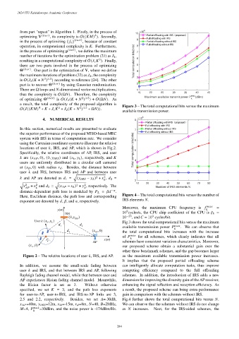
a result, the total complexity of the proposed algorithm is Figure 3 – The total computational bits versus the maximum
4
2 3.5
2
O( (( ) + + 1 + 2 ( + ) + Ω )).
available transmission power.
4. NUMERICAL RESULTS 8 10 6
Full offloading with IRS
In this section, numerical results are presented to evaluate 7 Partial offloading without IRS
the superior performance of the proposed MISO-based MEC Full offloading without IRS
system with IRS in terms of computation rate. We consider 6
using the Cartesian coordinate system to illustrate the relative
locations of user , IRS, and AP, which is shown in Fig.2. Total computation bits(bits) 5
Specifically, the relative coordinates of AP, IRS, and user
are ( , 0), (0, ) and ( , ), respectively, and 4
users are uniformly distributed in a circular cell centered
at ( , 0) with radius . Besides, the distance between
3
user and IRS, between IRS and AP and between user
√︃
2
2
and AP are denoted as 1 = ( − ) + , 2 =
2
10 20 30 40 50 60 70 80
√︃ √︃
2 2 2 2
+ and 3 = ( − ) + , respectively. The Number of IRS elements N
−
distance-dependent path loss is modeled by = .
Figure 4 – The total computational bits versus the number of
Here, Euclidean distance, the path loss and corresponding
IRS elements .
exponent are denoted by , , and , respectively.
=
Moreover, the maximum CPU frequency is
m
y () 9
IRS 10 cycles/s, the CPU chip coefficient of the CPU is =
3
(0, y IRS ) 10 −28 , and = 10 cycles/bit.
User k (,xy k ) Fig.3 shows the total computational bits versus the maximum
k
d 1 d 2 max
available transmission power . We can observe that
d 3 ( AP ,x 0 ) the total computational bits increases with the increase
max
of for all schemes, which clearly indicates that all
r x ()
m
d AP schemes have consistent variation characteristics. Moreover,
( D ,x 0 ) our proposed scheme obtain a substantial gain over the
other three benchmark schemes, and the gap becomes larger
Figure 2 – The relative locations of user , IRS, and AP. as the maximum available transmission power increases.
It implies that the proposed partial offloading scheme
In addition, we assume the small-scale fading between can intelligently allocate computation tasks, thus improve
user and IRS, and that between IRS and AP, following computing efficiency compared to the full offloading
Rayleigh fading channel model, while that between user and schemes. In addition, the introduction of IRS adds a new
AP experiences Rician fading channel model. Meanwhile, dimension for improving the diversity gain of the AP receiver,
the Rician factor is set as 3. Without otherwise enhancing the signal reflection and reception efficiency. As
specified, we set = 3, and the path loss exponents a result, the proposed scheme can bring extra performance
for user-to-AP, user-to-IRS, and IRS-to-AP links are 3, gain in comparison with the schemes without IRS.
2.5 and 2.2, respectively. Besides, we set =-30dB, Fig.4 further shows the total computational bits versus .
=40m, =12m, =-15m, =8m, =40, =2MHz, We can observe that the schemes without IRS do not change
=4, =30dBm, and the noise power is -174dBm/Hz. as increases. Next, for the IRS-aided schemes, the
– 284 –