
Page 27 - ITU Journal Future and evolving technologies Volume 2 (2021), Issue 4 – AI and machine learning solutions in 5G and future networks
P. 27
ITU Journal on Future and Evolving Technologies, Volume 2 (2021), Issue 4
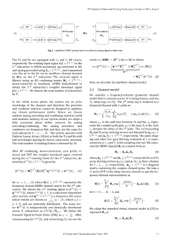
Fig. 1 – mmWave MIMO system based on a hybrid analog‐digital architecture.
The Tx and Rx are equipped with and RF chains, result (AXB) = (B ⊗ A) (X) to obtain
respectively. The training input signal s[ ] ∈ ℂ ×1 on the ( ) ( ) ∗
t h subcarrier is OFDM modulated, up‐converted to RF, (y ( ) [ ]) = (q ( ) F tr ⊗ W tr ) (H[ ])
⏟⏟⏟⏟⏟⏟⏟⏟⏟⏟⏟
and analog precoded using F ∈ ℂ × , and transmitted ( )
tr
over the air to the Rx via an mmWave channel denoted ( ) ∗
H[ ] t subcarrier The received signal is + W tr n ( ) [ ]. (2)
iltered using an RF combining matrix W ∈ ℂ × ,
tr
Next, we describe the mmWave channel model.
down‐converted to baseband, OFDM demodulated to
obtain the t h subcarrier’s complex baseband signal
y[ ] ∈ ℂ ×1 . We denote the total number of subcarriers 2.1 Channel model
by .
We consider a frequency‐selective geometric channel
model that is constant across training frames, and has
th
In the initial access phase, the system has no prior delay taps [4, 25]. The delay tap is modeled as a
knowledge of the channel, and therefore the precoder clustered channel with paths as
and combiner matrices cannot be designed to optimize
any chosen performance metric. Hence, we choose ∗
H = √ ∑ ( − )a ( )a ( ), (3)
random analog precoding and combining matrices (with ℓ=1 ℓ ℓ R ℓ T ℓ
unit modulus entries). In our system model, we adopt a
ℓ
fully connected phase shifter network for analog where is the path loss between Tx and Rx, repre‐
ℓ
precoding/combining. The analog precoders and sents the complex path gain, is the AoA, is the AoD,
ℓ
th
combiners are frequency‐ lat, and thus are the same for denotes the delay of the ℓ path. The corresponding
ℓ
Rx and Tx array steering vectors are denoted by a ( ) ∈
each subcarrier = 1, … , . The system operates with R ℓ
ℂ ×1 and a ( ) ∈ ℂ ×1 , respectively. The pulse shap‐
Uniform Linear Arrays (ULAs) at both the Tx and Rx with T ℓ
ing and other low pass iltering evaluated at is repre‐
half wavelength spacing be‐tween consecutive antennas.
The total number of training frames is denoted by . sented by ( ), and is the sampling interval. We repre‐
sent the MIMO channel H in a matrix form as
After RF combining, down‐conversion, zero pre ix re‐ H = A A , (4)
∗
moval and DFT, the complex baseband signal received R T
during the t h training frame for the t h subcarrier, de‐ where A ∈ ℂ × and A ∈ ℂ × contain the Rx and Tx
R
T
noted by y ( ) [ ] ∈ ℂ ×1 is given by array steering vectors a ( ) and a ( ) as their columns
ℓ
ℓ
R
T
for ℓ = 1, … , , respectively. ∈ ℂ × is a diagonal
q
y ( ) [ ] = W ( ) ∗ (H[ ]F ( ) ( ) ( ) [ ] + n ( ) [ ]), (1) matrix containing the complex channel gains. We take a
tr tr ‐point DFT of the delay‐domain channel to get the fre‐
quency domain representation as
−1
for = 1, … , where H[ ] ∈ ℂ × represents the H[ ] = ∑ H exp (− 2 ) = A [ ]A , (5)
∗
frequency domain MIMO channel matrix for the sub‐ =0 R T
th
carrier. We choose the training signal as s ( ) [ ] =
th
q ( ) ( ) [ ], where ( ) [ ] ∈ ℂ is a subcarrier‐dependent for = 0, … , − 1, and
pilot symbol, and q ( ) ∈ ℂ ×1 is a frequency‐ lat vector −1
1 2
whose entries are chosen as ( + ), where , ∈ [ ] = ∑ exp (− ) . (6)
√2
{−1, 1} and are uniformly distributed. The noise vec‐ =0
tor n ( ) [ ] is independently and identically distributed We adopt the extended virtual channel model in [25] to
across subcarriers as ( , I ). We de ine the
2
represent H as
transmit Signal‐to‐Noise Ratio (SNR) as = 1 2 . After
̃ ̃ ∗
compensating for ( ) [ ], and vectorizing (1), we use the H ≈ A A , (7)
R
T
© International Telecommunication Union, 2021 11