
Page 978 - 5G Basics - Core Network Aspects
P. 978
2 Transport aspects
13.2.1.3.2 Parameters controlled by the RPA procedure
The RPA function shall be used for adjustment of PMD parameters related to the RMC. These adjustments
are accomplished by a change to the bit loading, or set of subcarriers used for conveying RMC data. The
details of these adjustments are described in Table 13-6.
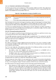
Table 13-6 – Reconfigurable parameters of the RPA function
Parameter Definition
RMC tone set Set of used subcarriers to be loaded with RMC data. The number of subcarriers used shall not
(RTS) exceed 512.
bRMC-i The number of bits per RMC subcarrier with valid values of 0 and from 2 to 6.
Both the receiver and transmitter shall support all valid bRMC-i values and shall support any change of these
values provided the resulting bRMC-i value is within the specified valid range. The values of bRMC-i shall also
not exceed the DPU-MIB parameter MAXBL-RMC for the corresponding direction of transmission.
The RTS may be modified beyond the set determined during the initialization (see RTSus and RTSds in
clause 12.3.4.2). If the RTS is modified, the new bit loading and re-ordered tone table of the RMC symbol
shall be recomputed as specified in clause 10.2.1.2.
13.2.1.3.3 Timing and synchronization for RPA
The FTU shall respond to the OLR command of OLR request type 4 within one superframe duration using
the responses defined in Table 9-16 (over RMC) and Table 11-19 (over eoc).
The new RMC parameters requested by the RPA shall be applied by both FTUs starting from the RMC
symbol of the sync frame of the superframe with the superframe count indicated in the OLR command of
OLR request type 4 sent by the initiating FTU.
13.2.1.4 L2TSA procedure
The L2TSA (L2 transmission schedule adaptation) procedure described in this clause is intended to modify
the transmission schedule of RMC symbols during L2.1 link state. The procedure may be applied during
both L2.1N and L2.1B link states.
The FTU-O shall initiate the L2TSA procedure when either of the following conditions are met in either
upstream or downstream or both directions of transmission:
• The SNRM is lower than MINSNRM and cannot be increased to L2_TARSNRM with an
ETR ≥ L2.1_ETR_min by using an SRA procedure (clause 13.2.1);
• The SNRM is higher than L2.1_MAXSNRM and cannot be decreased to L2_TARSNRM with an NDR ≤
L2.1_NDR_max by using an SRA procedure (clause 13.2.1).
The FTU-O shall poll the actual downstream SNRM through the eoc (see clause 11.2.2.13). The FTU-O shall
also observe the lom indicator bit to detect the critical decrease of margin.
The FTU-O may also initiate L2TSA for the case when the bit rate is inside the boundaries defined by the
DPU-MIB (L2.1_ETR_min, L2.1_NDR_max), for L2.1 performance optimization (adjusting the SNRM, or the
bit rate, or increasing power savings). The criteria to initiate L2TSA in this case is vendor discretionary.
The L2TSA procedure shall only be initiated by the FTU-O and shall include the following steps.
1) Upon detection of L2TSA conditions in the received RMC of upstream, downstream or both
directions, the FTU-O shall initiate the L2TSA procedure by sending an L2TSA request (OLR request
type 5, see Table 11-9) via the eoc that indicates the required transmission schedule for both
transmission directions. Once the L2TSA request has been sent, the FTU-O shall reject all OLR
requests type 1 and type 2 from the FTU-R with reason code "wait" until the L2TSA procedure has
been completed.
968